DVR-RT500-S
98
1
2
3
4
1
2
3
4
C
D
F
A
B
E
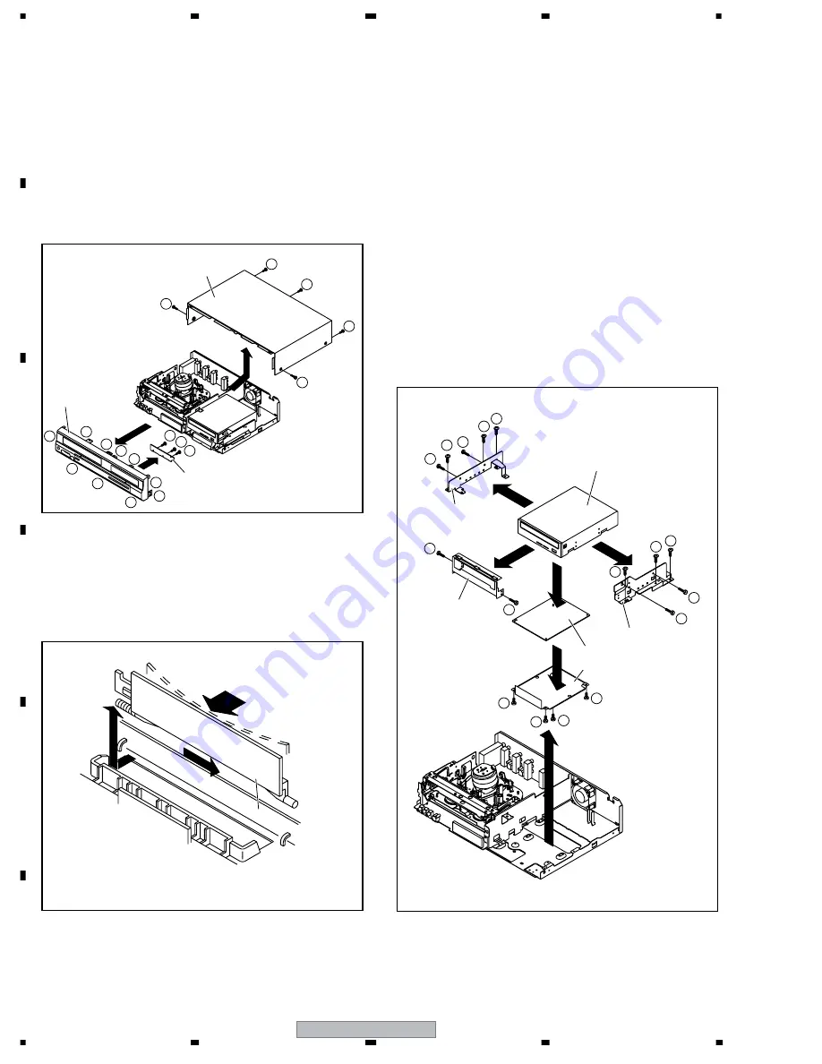
7.8 DISASSEMBLY
1-1: TOP CABINET AND FRONT CABINET
(Refer to Fig. 1-1)
1. Remove the 5 screws
1
.
2. Remove the Top Cabinet in the direction of arrow (A).
3. Disconnect the following connector: (CP681).
4. Unlock the 10 supports
2
.
5. Remove the Front Cabinet in the direction of arrow (B).
6. Remove the 3 screws
3
.
7. Remove the Operation PCB in the direction of arrow (C).
1-3: DECK CD AND DVD/HD MPEG PCB
(Refer to Fig. 1-3)
1. Remove the 2 screws
1
.
2. Remove the Deck Shield Assy in the direction of arrow
(A).
3. Remove the 6 screws
2
.
4. Disconnect the following connectors:
(CP504, CP1703, CP8301,CP8302, CP8303).
5. Remove the Deck CD Block in the direction of arrow (B).
6. Remove the 4 screws
3
.
7. Remove the MPEG Shield in the direction of arrow (C).
8. Disconnect the following connector: (CP4001).
9. Remove the DVD/HD MPEG PCB in the direction of
arrow (D).
10. Remove the 2 screws
4
.
11. Remove the DVD Angle (L) in the direction of arrow (E).
12. Remove the 2 screws
5
.
13. Remove the DVD Angle (R) in the direction of arrow
(F).
1-2: FLAP (Refer to Fig. 1-2)
1. Open Flap to 90
°
and flex in direction of arrow (A), at
the same time slide in direction of arrow (B).
2. Then lift in direction of arrow (C).
Fig. 1-1
Fig. 1-3
Fig. 1-2
1
1
1
1
3
3
3
3
3
3
3
2
2
2
2
2
2
5
5
2
2
4
4
1
1
2
2
2
2
2
2
2
2
1
Top Cabinet
Operation PCB
DVD Angle (L)
DVD Angle (R)
DVD/HD MPEG PCB
MPEG Shield
Deck Shield Assy
Deck CD
Flap
Front Cabinet
(A)
(A)
(D)
(C)
(B)
(E)
(F)
(B)
(C)
(A)
(B)
1. REMOVAL OF MECHANICAL PARTS AND P.C. BOARDS


