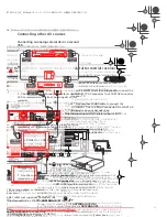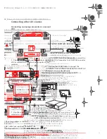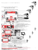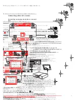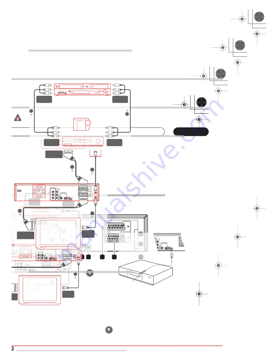
Connecting up
02
13
En
Chapter 2
Connecting up
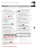
Rear panel connections
1
AC IN – Power inlet
2
Cooling fan
Do not obstruct the cooling fan vents.
3
COMPONENT VIDEO OUT
A high-quality video output for connecting to a TV or
monitor with a component video input.
4
VIDEO / AUDIO OUT
Standard video and stereo analog audio outputs for
connection to a TV or AV amplifier/receiver.
5
S-VIDEO OUT
A high-quality video output for connecting to a TV or
monitor with an S-Video input.
6
DIGITAL OUT
Optical digital audio jack for connecting to an AV
amplifier/receiver, Dolby Digital/DTS/MPEG decoder or
other equipment with a digital input.
7
CONTROL IN
Use to control this recorder from the remote sensor of
another Pioneer component with a
CONTROL OUT
terminal and bearing the Pioneer
mark. Connect the
CONTROL OUT
of the other component to the
CONTROL
IN
of this recorder using a mini-plug cord.
8
G-LINK™
Use to connect the supplied G-LINK™ cable to enable
the GUIDE Plus+
®
system to control an external satellite
receiver, etc.
9
AV2(INPUT 1/DECODER) AV connector
Audio/video input/output SCART-type AV connector for
connecting to another video component with a SCART
connector. The input accepts video, S-video and RGB.
See
on page 111 for how to set this up.
10 AV1(RGB)-TV AV connector
Audio/video output SCART-type AV connector for
connecting to a TV or other equipment with a SCART
connector. The video output is switchable between video,
and RGB (though must be set to Video for VHS output).
See page
on page 111 for how to set this up.
11 ANTENNA IN (RF IN)/OUT
Connect your TV antenna to the
ANTENNA IN (RF IN)
jack. The signal is passed through to the
ANTENNA OUT
jack for connection to your TV.
Front panel connections
There are more connections available on the front panel.
12 INPUT2 VIDEO / AUDIO
Standard video and stereo analog audio inputs,
especially suitable for camcorders, game consoles,
portable audio, etc.
OUT
IN
ANTENNA
AV 2 ( INPUT1/DECODER )
AV 1 (RGB) - TV
IN
L
Y
P
B
P
R
R
HDD / DVD
DIGITAL
OUT
OPTICAL
S-VIDEO
OUT
VIDEO
OUT
COMPONENT
VIDEO OUT
AC IN
AUDIO
OUT
G-LINK
HDD / DVD
CONTROL
HDD / DVD
1
2
3
4
6
5
7
8
9
10
11
INPUT2
VIDEO
L (MONO)
•
AUDIO
•
R
HDD/DVD
S-VIDEO
12
13
DVRRT601HS_WV_EN.book 13 ページ 2005年8月3日 水曜日 午後3時31分
Downloaded From DvDPlayer-Manual.com Pioneer Manuals
15
En
Easy connections
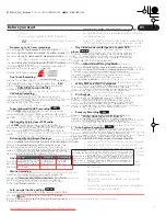
The setup described below is a basic setup that allows you to watch and record TV programs, and play discs. Other
types of connections are explained starting on the following page.
Important
• These connections use SCART cables (not supplied). If your TV does not have a SCART connection, see the
following page for connecting up using the supplied audio/video cable.
• The
AV1(RGB)-TV
AV connector can output ordinary (composite), S-video or RGB video, plus stereo analog audio.
The
AV2(INPUT 1/DECODER)
connector accepts ordinary, S-video and RGB video input, as well as stereo analog
audio. See
on page 111 and
on page 111 for how to set them up.
1
• Before making or changing any rear panel connections, make sure that all components are switched off and
unplugged from the wall outlet.
1
Connect the cable from the antenna/cable TV
outlet to the ANTENNA IN (RF IN) jack on this
recorder.
2
Use another RF antenna cable to connect the
ANTENNA OUT of this recorder to the antenna input
on your TV.
3
Use a SCART cable (not supplied) to connect the
AV1(RGB)-TV AV connector on this recorder to the
SCART AV connector on your TV.
Tip
• This recorder has a ‘through’ function which allows
you to record a TV program from the built-in TV tuner
in this recorder while watching a video playing on a
separate video component. (To use this feature when
the recorder is in standby,
Power Save
must be set
to
Off
—see
on page 109).
Note
1 For better quality video during HDD/DVD playback and recording, you can use the
S-Video
and
RGB
settings with AV connections. However,
for VHS playback and recording, the
AV1 Out
and
AV2/L1 In
settings (on page 111) must be set to
Video
.
TV
Antenna/cable TV
wall outlet
OUT
IN
ANTENNA
AV 2 ( INPUT1/DECODER )
AV 1 (RGB) - TV
IN
L
Y
P
B
P
R
R
HDD / DVD
DIGITAL
OUT
OPTICAL
S-VIDEO
OUT
VIDEO
OUT
COMPONENT
VIDEO OUT
AC IN
AUDIO
OUT
G-LINK
HDD / DVD
CONTROL
HDD / DVD
SCART AV
CONNECTOR
ANTENNA
IN
1
3
2
DVRRT601HS_WV_EN.book 15 ページ 2005年8月3日 水曜日 午後3時31分
Downloaded From DvDPlayer-Manual.com Pioneer Manuals
17
En
Connecting to a cable box, satellite receiver or digital terrestrial receiver
If you have a cable, satellite or digital terrestrial receiver with a built-in decoder, connect it to this recorder and your TV
as shown on this page.
1
If you are using a separate decoder box for your cable/satellite TV, set up following the
instructions on the next page.
Using the setup on this page you can:
• Record any channel by selecting it on the cable box, satellite receiver or digital terrestrial receiver.
• Change channels and set timer recordings on the external receiver using the GUIDE Plus+
®
system (via the
G-LINK™ cable, and after setting up).
Important
• Do not connect this recorder to your TV ‘through’ an external VCR, satellite receiver or other component. Always
connect each component directly to your TV or AV amplifier/receiver.
1
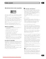
Connect RF antenna cables as shown.
This enables you to watch and record TV channels.
2
Use a SCART cable (not supplied) to connect the
AV1(RGB)-TV AV connector to a SCART AV connector
on your TV.
This enables you to watch discs.
3
Use another SCART cable to connect the
AV2(INPUT 1/DECODER) AV connector to a SCART AV
connector on your cable box/satellite/digital
terrestrial receiver.
This enables you to record scrambled TV channels.
4
Plug the supplied G-LINK™ cable to the G-LINK™
jack.
This enables you to control the tuner in the external
receiver using the GUIDE Plus+
®
system.
Position the IR transmitter end of the G-LINK™ cable so
that the IR receiver on your cable/satellite/digital
terrestrial receiver will pick up the control signals (see
diagram).
See the manual that came with your cable/satellite/
digital terrestrial receiver if you’re not sure where the IR
receiver is on the front panel. Alternatively, experiment
with the remote control, operating it from very close
range until you find the place where the receiver
responds.
Tip
• This recorder has a ‘through’ function which allows
you to record a TV program from the built-in TV tuner
in this recorder while watching a video playing on a
separate video component. (To use this feature when
the recorder is in standby,
Power Save
must be set
to
Off
—see
on page 109).
Note
1 The diagram shows SCART video connections, but you can alternatively use any of the other audio/video connections.
TV
Satellite dish/
antenna/cable TV
wall outlet
Cable/Satellite/
Digital Terrestrial
receiver
OUT
IN
ANTENNA
AV 2 ( INPUT1/DECODER )
AV 1 (RGB) - TV
IN
L
Y
P
B
P
R
R
HDD / DVD
DIGITAL
OUT
OPTICAL
S-VIDEO
OUT
VIDEO
OUT
COMPONENT
VIDEO OUT
AC IN
AUDIO
OUT
G-LINK
HDD / DVD
CONTROL
HDD / DVD
SCART AV
CONNECTOR
SCART AV
CONNECTOR
ANTENNA
IN
ANTENNA
IN (RF IN)
ANTENNA
OUT
1
1
2
3
1
4
AV 2 ( INPUT1/D
AV 1 (RGB) -
IN
L
R
/ DVD
DIGITAL
OUT
OPTICAL
S-VIDEO
OUT
VIDEO
OUT
ONENT
O OUT
AUDIO
OUT
G-LINK
/ DVD
CONTROL
HDD / DVD
G-LINK cable
DVRRT601HS_WV_EN.book 17 ページ 2005年8月3日 水曜日 午後3時31分
Downloaded From DvDPlayer-Manual.com Pioneer Manuals
19
En
Connecting an external decoder box (2)
If you only have a decoder, connect it to this recorder and your TV as shown on this page.
1
Using the setup on this page you can:
• Record scrambled channels received using the recorder’s built-in TV tuner.
Important
• Do not connect this recorder ‘through’ a VCR, satellite receiver or cable box. Always connect each component
directly to your TV or AV amplifier/receiver.
1
Connect RF antenna cables as shown.
This enables you to watch and record TV channels.
2
Use a SCART cable (not supplied) to connect the
AV1(RGB)-TV AV connector to a SCART AV connector
on your TV.
This enables you to watch discs.
3
Use another SCART cable to connect the
AV2(INPUT 1/DECODER) AV connector to a SCART AV
connector on your decoder box.
This enables you to record scrambled TV channels.
Note
1 In order to use this setup, you will need to make the following settings from the Initial Setup menu:
• Set the
AV2/L1 In
setting to
Decoder
from the Initial Setup menu (see
on page 111).
• From the
Manual CH Setting
screen, set the
Decoder
setting for the scrambled channels to
On
(see
on page 110).
TV
Antenna/cable TV
wall outlet
Decoder
OUT
IN
ANTENNA
AV 2 ( INPUT1/DECODER )
AV 1 (RGB) - TV
IN
L
Y
P
B
P
R
R
HDD / DVD
DIGITAL
OUT
OPTICAL
S-VIDEO
OUT
VIDEO
OUT
COMPONENT
VIDEO OUT
AC IN
AUDIO
OUT
G-LINK
HDD / DVD
CONTROL
HDD / DVD
SCART AV
CONNECTOR
SCART AV
CONNECTOR
ANTENNA
IN
1
2
3
1
DVRRT601HS_WV_EN.book 19 ページ 2005年8月3日 水曜日 午後3時31分
Downloaded From DvDPlayer-Manual.com Pioneer Manuals
21
En
Connecting other AV sources
Connecting an analog camcorder or a second
VCR
1
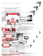
Connect a set of audio and video outputs of your
VCR or camcorder to the front panel inputs of this
recorder.
This enables you to record tapes from your camcorder or
second VCR.
• You can't record the S-video input signal to VHS tape.
• This connection isn’t necessary if you are using the
AV2(INPUT 1/DECODER)
SCART connector for
audio/video input and output (as explained in step 1).
2
Connect a set of audio and video inputs of your
camcorder or VCR to a set of outputs on this
recorder.
This enables you to record from this recorder to your
camcorder or second VCR.
• The
S-VIDEO
and
COMPONENT
video jacks output a
video signal during HDD and DVD playback only. For
VHS playback, connect using the
VIDEO OUT
jack.
• Alternatively, you can use the
AV2(INPUT 1/
DECODER)
SCART connector for audio/video input
and output with just one SCART cable.
Plugging in
After checking all the connections, plug in the recorder.
1
Use the supplied power cable to connect this
recorder to a power outlet.
Analog camcorder
VCR
OPEN/
CLOSE
COPY
SELECT
VHS AUTO
COPY
COPY
REC
PLAY
VHS/HDD/DVD
VHS
EJECT
INPUT2
STANDBY/ON
VIDEO
L (MONO)
•
AUDIO
•
R
HDD/DVD
S-VIDEO
VHS
HDD
DVD
START
AUDIO/VIDEO
INPUT
AUDIO/VIDEO
OUTPUT
1
2
AUDIO/VIDEO
OUTPUT
AUDIO/VIDEO
INPUT
DVRRT601HS_WV_EN.book 21 ページ 2005年8月3日 水曜日 午後3時31分
Downloaded From DvDPlayer-Manual.com Pioneer Manuals
Summary of Contents for DVR-RT604H-S
Page 6: ......
Page 8: ......
Page 10: ......
Page 12: ......
Page 14: ......
Page 16: ......
Page 18: ......
Page 20: ......
Page 22: ......
Page 24: ......
Page 26: ......
Page 28: ......
Page 30: ......
Page 32: ......
Page 34: ......
Page 36: ......
Page 38: ......
Page 40: ......
Page 42: ......
Page 44: ......
Page 48: ......
Page 50: ......
Page 52: ......
Page 54: ......
Page 56: ......
Page 58: ......
Page 60: ......
Page 62: ......
Page 64: ......
Page 66: ......
Page 68: ......
Page 70: ......
Page 72: ......
Page 74: ......
Page 76: ......
Page 78: ......
Page 80: ......
Page 82: ......
Page 84: ......
Page 86: ......
Page 88: ......
Page 90: ......
Page 92: ......
Page 94: ......
Page 96: ......
Page 98: ......
Page 100: ......
Page 102: ......
Page 104: ......
Page 106: ......
Page 108: ......
Page 110: ......
Page 112: ......
Page 114: ......
Page 116: ......
Page 118: ......
Page 120: ......
Page 122: ......
Page 124: ......
Page 126: ......
Page 128: ......
Page 130: ......
Page 132: ......

