PRO-1010HD
182
1
2
3
4
1
2
3
4
C
D
F
A
B
E
A
1
, A
0
(A
- 1
)
V
SS
V
CC
WE
CE
A
19
~ A
2
OE
DQ
31
~ DQ
0
DW/W
WP
ACC
STB
STB
Control
Circuit
(Command
Register)
Erase Circuit
Input/Output
Buffer
Write Circuit
Chip Enable
Output Enable
Circuit
Data Latch
Low Vcc DET.
Circuit
Write / Erase
Pulse Timer
Y Decoder
X Decoder
Y Gate
33,554,432
Cell Matrix
Address Latch
57-51, 40-34,
11-8
12, 18, 28,
58, 63, 73
17, 27, 33,
64, 74, 79
7, 6,
78
81
80
88
87
82
86
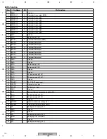
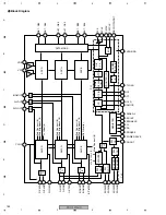
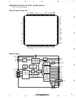
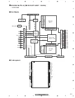
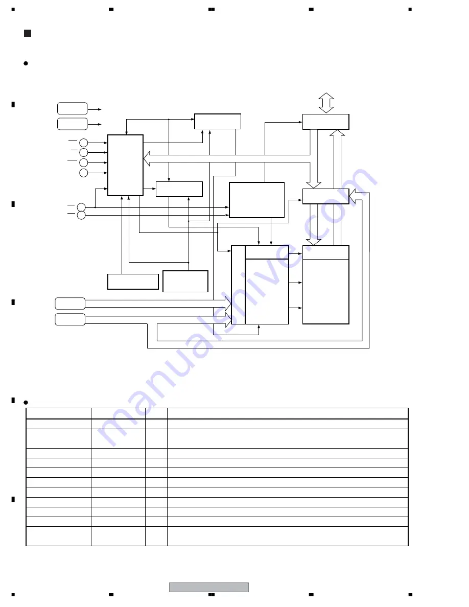
Block Diagram
MBM29PL3200BE70PFV (RGB ASSY : IC7152)
• Page Mode Flash Memory
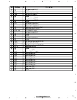
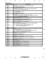
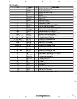
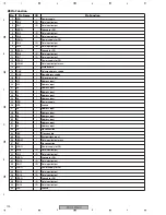
No.
Pin Name
I/O
Pin Function
57-51, 40-34, 11-6, 78 A
19
- A
0
, A
-1
I
Address input
78-75, 72-65, 62-59,
32-19, 26-19, 16-13
DQ
31
- DQ
0
I/O
Data input/output
80
CE
I
Chip enable
81
OE
I
Output enable
86
WE
I
Write enable
82
DW/W
I
16 bit, 32 bit mode switch
87
WP
I
Write protect
88
ACC
I
Acceleration
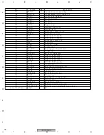
17, 27, 33, 64, 74, 79
V
SS
−
Ground
12, 18, 28, 58, 63, 73
V
CC
−
Power supply
1-5, 41-50,
83-85, 89, 90
N.C.
−
No connection
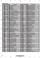
Pin Function


