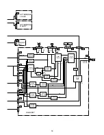
PDP-433CMX, PDP-433MXE
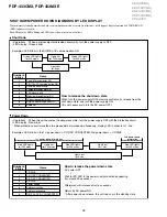
• Operations : When a microcomputer detected abnormality, turn the power supply to OFF.
• LED display : Green blinks
How to release the shut down state
When turn the power supply ON by remote control units, release from the
shut down state, and turn the power supply ON.
(It is not necessary to turn the AC power OFF.)
How to release the power down state
AC power OFF
↓
Wait for PD LED in the power supply module disappearing
(for around 30 seconds).
↓
Afterwards, wait moreover for five seconds.
↓
Return by AC power ON.
* After power down release, this unit rises up in the standby state.
Examples: LED blinks in the DIGITAL-IIC communication NG
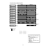
• Operations : When this unit becomes the dangerous state, turn the power supply OFF with the protection circuit.
• LED display : Red blinks
* When protection circuit more than two places almost worked simultaneously, display LED in order to 1st - 2nd.
Examples: LED blinks in the 1st power down = Y-DC/DC CONVERTER, 2nd power down = Y-DRIVE
Number of
blinks
Name
1
Panel Microcomputer NG
2
DIGITAL-IIC communication NG
3
Dewdrop abnormality
4
Temperature abnormality
5
FAN abnormality
6
Module microcomputer NG
7
Wide microcomputerNG
8
RGB-IIC communication NG
9
Audio NG
Number of
blinks
Name
1
Y-DRIVE
2
Y-DC/DC CONVERTER
3
X-DC/DC CONVERTER
4
X-DRIVE
5
Power supply
6
Address junction
7
Address resonance
8
DIGITAL-DC/DC CONVERTER
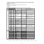
SHUT DOWN/POWER DOWN DIAGNOSIS BY LED DISPLAY
Shut Down
Power Down
Green LED lights
for 200 msec.
Lights out
for 3 sec
Green LED lights
for 200 msec.
Lights out
for 100 msec
When internal circuit abnormality and other operation abnormality occurred from this unit, self-diagnose display function by STANDBY/ON
(LED) indicator is loaded.
Each NG point by LED blinking and a PD (power down) point are as follows.
1st power-down information
2nd power-down
information
Red LED lights
for 200 msec.
Lights out
for 3 sec
Lights out
for 1 sec
Red LED lights
for 200 msec.
Lights out
for 100 msec
Red LED lights
for 200 msec.
38
PRO800HD,
PRO1000HD,
PDP433CMX,
PDP503CMX,
PDP4300
Summary of Contents for Elite PRO-506PU
Page 2: ......
Page 8: ... 2 4 SI PG06003 A Warranty Claim Example 8 ...
Page 14: ...14 Quick Reference G 3 to G 8 Power Down Shut Down Trap Switch Reset Service Remotes ...
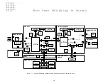
Page 23: ...23 Models PDP433PU PDP503PU Block Diagrams Shut Down Power Down Diagnosis ...
Page 30: ...30 Models PDP433CMX PDP503CMX PDP4300 PRO800HD HDI PRO1000HD HDI ...
Page 31: ...31 Block Diagrams Basic Service Factory Mode Shut Down Power Down Diagnosis ...
Page 48: ...48 Models PDP434CMX PDP504CMX PDP505CMX PDP4304 PDP4314 PDP5004 PDP5014 PRO810HD PRO1010HD ...
Page 49: ...49 Block Diagrams Operation LED Statuses Power Down Shut Down Diagnosis ...
Page 72: ...72 Models PDP436PU PDP506PU PRO436PU PRO506PU ...
Page 73: ...73 Block Diagrams Operation LED Statuses Shut Down Power Down Diagnosis System Reset ...
Page 82: ...82 Models PDP4270HD PDP4271HD PDP5070HD PDP5071HD PDP6070HD PDP6071HD PRO507PU PRO607PU ...
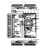
Page 87: ...87 Models PDP6070HD PDP6071HD PRO607PU Block Diagrams on the next two pages ...
Page 120: ...120 Scan IC Troubleshooting Blue Glue Removal IC Removal ...
Page 121: ......
Page 142: ...142 ...

