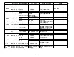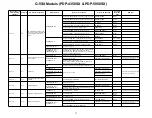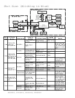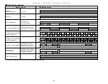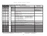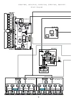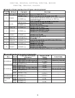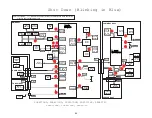
Defective points assumed from the number of times of LED flashing
No. of times of LED flashing
Category
∗
1
Site detected as
defective
Possible defective points (representative examples)
OSD when detected
(warning message)
LEDs on the panel
LEDs on the MR
Red
Blue
Red
Blue
Blue 1
Red
SD
Panel drive IC
∗
2
None
Blue 2
Red
Module section IIC
∗
2
None
Blue 3
Red
Power decrease of
DIGITAL-DC-DC
∗
2
None
Blue 4
Red
Panel having abnormally
high temperature
∗
2
Power off.
Internal temperature is too high.
Check temperature around PDP. [SD04]
∗6
Blue 5
Red
Short-circuiting of the
speakers
∗
2
Internal protection circuit turns power off.
Is there a short in speaker cable? (SD05)
Red
Blue 6
Module microcomputer
Disconnection of the system cable
Defective module microcomputer or its peripheral circuits of the panel (Refer to the service manual of the PDP-436PU or
PDP-506PU.)
Defective main microcomputer (IC5206)
Failure in communication (TXD_MD, RXD_MD, REQ_MD) between the panel's module microcomputer and IC5206 (main
microcomputer)
None
Red
Blue 7
3-wire serial connection
of the main section
Defective IC5002 or its peripheral circuits
Failure in communication (TXD_IF, RXD_IF, CLK_IF, CE_IF, REQ_IF, BUSY_IF) between IC5002 and IC5206 (main
microcomputer)
Defective IC7001 or its peripheral circuits
Failure in communication (TXD_IC3, RXD_IC3, CLK_IC3, IC3_CE, REQ_IC3, BUSY_IC3) between IC7001 and IC5206
(main microcomputer)
None
Red
Blue 8
IIC of the main section
Defective U4401 (FE1) or its peripheral circuits
Defective U4402 (FE2) or its peripheral circuits
Defective IC4401 (MPX) or its peripheral circuits
∗
3
Defective IC4801 (AV_SW) or its peripheral circuits
Defective IC4702 (RGB_SW) or its peripheral circuits
Defective IC5602 (CCD) or its peripheral circuits
Defective ICxxxx (GCR) or its peripheral circuits
∗
4
Defective IC6003 (M-VDEC) or its peripheral circuits
Defective IC6001 (S-VDEC) or its peripheral circuits
∗5
Defective IC6201 (ADC) or its peripheral circuits
Defective IC6404 (HDMI) or its peripheral circuits
Defective IC7202 (PLK-T) or its peripheral circuits
Defective ICxxxx (PLK-R) or its peripheral circuits
Defective IC5405 (TTX-COM, TTX-BSY) or its peripheral circuits
∗
3
Defective IC5202 (MA-EEP) or its peripheral circuits
Failure in communication (SCL_AV, SDA_AV, SCL_MA, SDA_MA, SCL_EP, SDA_EP, SCL_HDCP, SDA_HDCP)
between one of the above devices and IC5206 (main microcomputer)
None
Red
Blue 9
Main microcomputer
Defective IC5206 (main microcomputer)
Failure in communication (TXD_IF, RXD_IF, CLK_IF, CE_IF, BUSY_IF) between IC5206 (main microcomputer) and
IC5002
None
Red
Blue 10
Fan
Failure in the fan motor, or the fan stopped because of dust attached to the fan
None
Red
Blue 11
MR or unit having abnormally
high temperature
The Media Receiver or the unit being used at high temperature
Power off.
Internal temperature is too high.
Check temperature around media receiver. [SD011]
Red
Blue 12
Digital tuner
Defective DTV tuner
Failure in communication (TXD_DT, RXD_DT) between the digital tuner and IC5206 (main microcomputer)
None
Red
Blue 13
ASIC power supply (DC-DC) Defective U4201 (DD_CON) or short-circuiting elsewhere
∗6
None
PD
Red 2
Red
POWER
∗
2
None
Red 3
Red
SCAN
∗
2
None
Red 4
Red
SCN-5V
∗
2
None
Red 5
Red
Y-DRV
∗
2
None
Red 6
Red
Y-DCDC
∗
2
None
Red 7
Red
Y-SUS
∗
2
None
Red 8
Red
ADRS
∗
2
None
Red 9
Red
X-DRV
∗
2
None
Red 10
Red
X-DCDC
∗
2
None
Red 11
Red
X-SUS
∗
2
None
Red 15
Red
UNKNOWN
∗
2
None
Red 12
Red
D-DCDC
∗
2
None
Red 13
Red
IC4
∗
2
None
∗
1: Shutdown (SD) is a protective operation controlled by the microcomputer, and you can turn on the unit
again using the remote control unit. Power-down (PD) is a protective operation activated by the circuitry
and can be reset after AC power is off for about 1 minute.
∗
2: Refer to the service manual of the PDP-436PU or PDP-506PU.
∗
3: Only for EU and IRD model.
∗
4: Only for J model.
∗
5: Except for US model.
∗
6: Only for one-body model.
80
PDP436PU, PDP506PU, PRO436PU, PRO506PU
Summary of Contents for Elite PRO-506PU
Page 2: ......
Page 8: ... 2 4 SI PG06003 A Warranty Claim Example 8 ...
Page 14: ...14 Quick Reference G 3 to G 8 Power Down Shut Down Trap Switch Reset Service Remotes ...
Page 23: ...23 Models PDP433PU PDP503PU Block Diagrams Shut Down Power Down Diagnosis ...
Page 30: ...30 Models PDP433CMX PDP503CMX PDP4300 PRO800HD HDI PRO1000HD HDI ...
Page 31: ...31 Block Diagrams Basic Service Factory Mode Shut Down Power Down Diagnosis ...
Page 48: ...48 Models PDP434CMX PDP504CMX PDP505CMX PDP4304 PDP4314 PDP5004 PDP5014 PRO810HD PRO1010HD ...
Page 49: ...49 Block Diagrams Operation LED Statuses Power Down Shut Down Diagnosis ...
Page 72: ...72 Models PDP436PU PDP506PU PRO436PU PRO506PU ...
Page 73: ...73 Block Diagrams Operation LED Statuses Shut Down Power Down Diagnosis System Reset ...
Page 82: ...82 Models PDP4270HD PDP4271HD PDP5070HD PDP5071HD PDP6070HD PDP6071HD PRO507PU PRO607PU ...
Page 87: ...87 Models PDP6070HD PDP6071HD PRO607PU Block Diagrams on the next two pages ...
Page 120: ...120 Scan IC Troubleshooting Blue Glue Removal IC Removal ...
Page 121: ......
Page 142: ...142 ...


