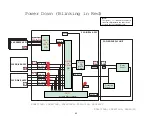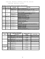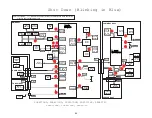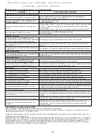
When replacing the Power Supply Unit, it is necessary to perform the following connector changes.
Otherwise the unit cannot work properly and the unit may be damaged.
Therefore perform these connector settings without fail when replacing the Power Supply Unit. ( before power on the unit)
u
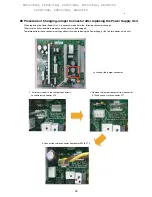
1. As for service parts, the Jumper connector is
connected at connector P10.
Location of the jumper connector
Procedure of Changing Jumper Connector after replacing the Power Supply Unit
2. Remove the jumper connector from connector
P10 and connect it to connector P11.
3. Connect the cable connector from power SW to P10.
98
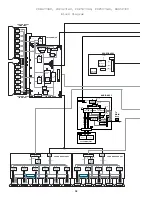
PDP4270HD, PDP4271HD, PDP5070HD, PDP5071HD, PRO507PU
PDP6070HD, PDP6071HD, PRO607PU
Summary of Contents for Elite PRO-506PU
Page 2: ......
Page 8: ... 2 4 SI PG06003 A Warranty Claim Example 8 ...
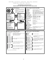
Page 14: ...14 Quick Reference G 3 to G 8 Power Down Shut Down Trap Switch Reset Service Remotes ...
Page 23: ...23 Models PDP433PU PDP503PU Block Diagrams Shut Down Power Down Diagnosis ...
Page 30: ...30 Models PDP433CMX PDP503CMX PDP4300 PRO800HD HDI PRO1000HD HDI ...
Page 31: ...31 Block Diagrams Basic Service Factory Mode Shut Down Power Down Diagnosis ...
Page 48: ...48 Models PDP434CMX PDP504CMX PDP505CMX PDP4304 PDP4314 PDP5004 PDP5014 PRO810HD PRO1010HD ...
Page 49: ...49 Block Diagrams Operation LED Statuses Power Down Shut Down Diagnosis ...
Page 72: ...72 Models PDP436PU PDP506PU PRO436PU PRO506PU ...
Page 73: ...73 Block Diagrams Operation LED Statuses Shut Down Power Down Diagnosis System Reset ...
Page 82: ...82 Models PDP4270HD PDP4271HD PDP5070HD PDP5071HD PDP6070HD PDP6071HD PRO507PU PRO607PU ...
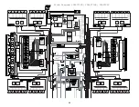
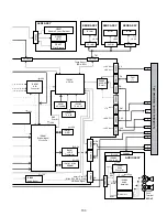
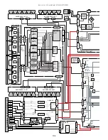
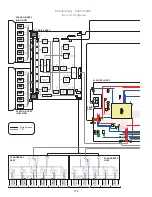
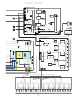
Page 87: ...87 Models PDP6070HD PDP6071HD PRO607PU Block Diagrams on the next two pages ...
Page 120: ...120 Scan IC Troubleshooting Blue Glue Removal IC Removal ...
Page 121: ......
Page 142: ...142 ...

