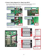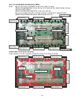
Scanning PKG: 9 screws
How to remove/reattach the Board Assy (PKGs)
Notes:
· Be sure not to drop a screwdriver or screw on a PKG or a cable.
· When removing/reattaching a screw, be sure not to leave any tiny metal shavings, because
they may cause a failure.
· Before removing Signal Relay PKGs, remove the heat sink.
· Be sure not to apply any stress to a PKG, connector, or cable when reattaching them.
· Reattach Signal Relay PKGs before reattaching the heat sink.
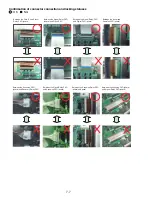
Confirmation of connector connection
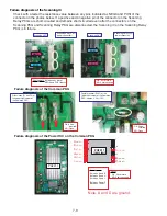
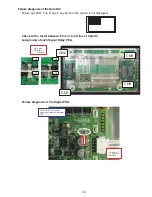
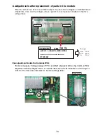
Check whether or not the connectors indicated by circles are correctly connected.
Common Branch PKG
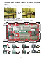
(upper): One screw
Digital PKG:
4 screws
Common Branch PKG
(lower): One screw
Signal Relay PKG
(upper left): 4 screws
Signal Relay PKG (upper
center): 5 screws
Signal Relay PKG (upper
right): 5 screws
Signal Relay PKG
(lower right): 5 screws
Signal Relay PKG
(lower center): 5 screws
Signal Relay PKG
(lower left): 4 screws
Signal Relay PKG
(upper left): 7 connectors
Common board:
10 connectors
Scanning PKG:
8 connectors
Signal Relay PKG (upper
center): 10 connectors
Signal Relay PKG (upper
right): 8 connectors
Signal Relay PKG (lower
right): 8 connectors
Signal Relay PKG (lower
center): 10 connectors
Signal Relay PKG (lower
left): 8 connectors
Scanning Relay PKG
(upper): 5 connectors
Scanning Relay PKG
(lower): 5 connectors
Scanning Relay PKG
(upper): 6 screws
Scanning Relay PKG
(lower): 5 screws
Heat sink: 17 screws
Heat sink: 17 screws
Common PKG: 8 screws
Recovery Relay PKG :11screws
Digital PKG:
8 connectors
Common branch PKG
7-6
Summary of Contents for Elite PureVision PRO 1410HD
Page 5: ...2 3 ...
Page 6: ...2 4 ...
Page 8: ...SPECIFICATIONS PDP 614MX 3 1 ...
Page 9: ... PRO 1410HD 3 2 ...
Page 10: ...TABLE OF SIGNAL SUPPORTED PDP 614MX 4 1 ...
Page 11: ...4 2 ...
Page 12: ...4 3 PRO 1410HD ...
Page 13: ...4 4 ...
Page 14: ...PANEL FACILITIES 5 1 PDP 614MX ...
Page 15: ...5 2 ...
Page 16: ...5 3 PRO 1410HD ...
Page 17: ...5 4 ...
Page 32: ...7 11 ...
Page 44: ...All white signal All white signal 8 12 ...
Page 50: ... Fig 1 CCD PWB Pattern Diagram A B D E 3 3V 6V C 8 18 ...
Page 51: ...8 19 Check point MAIN PWB ...
Page 52: ...8 20 232C PWB ...
Page 53: ...8 21 CLT PWB ...
Page 54: ...8 22 PWR PWB ...
Page 55: ...8 23 LED PWB ...
Page 56: ...8 24 SENB PWB ...
Page 57: ...8 25 SENC PWB ...
Page 58: ...8 26 SEND PWB ...
Page 59: ...AUDIO PWB 8 27 ...
Page 60: ...8 28 CCD PWB PX A only ...

