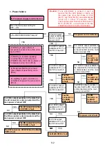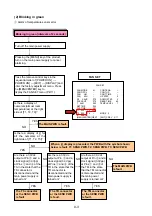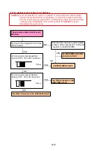
(2) Blinking in green
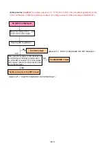
Alarm of te
mperature sensor error
YES
NO
The TS connector
or the SENC PWB
is fault.
NO
YES
The TR connector
or the SEND PWB
is fault.
Is there a display of
numerals (almost room
temperatures) at the right
side of [T1, T2, T3]?
YES
NO
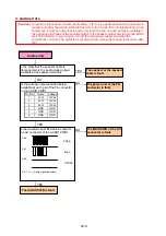
When a [-] display is presented, the PWB with the symbol shown
below is fault. T1: SEND PWB, T2: SENB PWB, T3: SENC PWB
Are there a 3.3Vdc
output at Pin and
a
clock signal (3.3Vpp)
at Pins and of the
TR in the state that the
TR connector is
disconnected and the
main power supply is
turned on?
Are there a 3.3Vdc
output at Pin
and a
clock signal (3.3Vpp)
at Pins
and
of
the TM in the state
that the TM connector
is disconnected and
the main power
supply is turned on?
YES
The TM connector
or the SENB PWB
is fault.
NO
The MAIN PWB is fault.
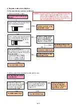
Is there a display of [-] for
all the numerals at the
right side of [T1, T2, T3]?
NO
YES
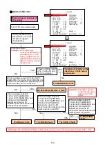
Press the remove control keys in the
sequential order of [POWER ON]
→
[POWER ON]
→
[EXIT]
→
[DISPLAY] and
enter the factory adjustment menu. Press
the [MENU/ENTER] key to
display the FAN SET menu (P2/11).
Blinking in green (intervals of 2 seconds)
FAN SET
Turn off the main power supply.
Pressing the [MENU] key of the product,
turn on the main power supply to cancel
alarming.
FAN SET
FAN MODE
H
CONT ENA
–
FAN OFF/L
–
CONT UP
–
FAN L/M
–
CONT TIME
–
FAN M/H
–
UP STEP
2
SF SAVE
075
DOWN STEP
2
PLE SAVE
070
READ TIME
60
T ALM
095
TEMP LEVEL
1
RET TME
030
PLE TIME
001
T1 030 T2 025
T3 030 T4 –
MODE 2
IC ERROR
–
[MENU/ENTER] NEXT
[EXIT] PREV 2/11
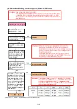
The MAIN PWB
is fault.
Are there a 3.3Vdc
output at Pin and a
clock signal (3.3Vpp)
at Pins and of the
TS in the state that the
TS connector is
disconnected and the
main power supply is
turned on?
8-3
Summary of Contents for Elite PureVision PRO 1410HD
Page 5: ...2 3 ...
Page 6: ...2 4 ...
Page 8: ...SPECIFICATIONS PDP 614MX 3 1 ...
Page 9: ... PRO 1410HD 3 2 ...
Page 10: ...TABLE OF SIGNAL SUPPORTED PDP 614MX 4 1 ...
Page 11: ...4 2 ...
Page 12: ...4 3 PRO 1410HD ...
Page 13: ...4 4 ...
Page 14: ...PANEL FACILITIES 5 1 PDP 614MX ...
Page 15: ...5 2 ...
Page 16: ...5 3 PRO 1410HD ...
Page 17: ...5 4 ...
Page 32: ...7 11 ...
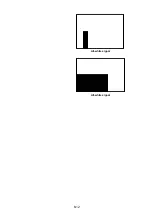
Page 44: ...All white signal All white signal 8 12 ...
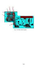
Page 50: ... Fig 1 CCD PWB Pattern Diagram A B D E 3 3V 6V C 8 18 ...
Page 51: ...8 19 Check point MAIN PWB ...
Page 52: ...8 20 232C PWB ...
Page 53: ...8 21 CLT PWB ...
Page 54: ...8 22 PWR PWB ...
Page 55: ...8 23 LED PWB ...
Page 56: ...8 24 SENB PWB ...
Page 57: ...8 25 SENC PWB ...
Page 58: ...8 26 SEND PWB ...
Page 59: ...AUDIO PWB 8 27 ...
Page 60: ...8 28 CCD PWB PX A only ...

