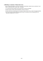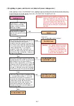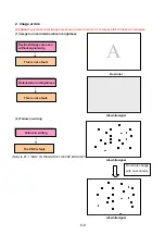
4. Remote control not effective
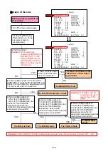
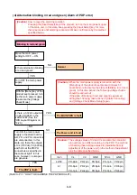
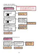
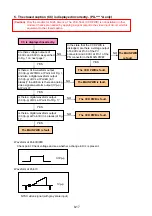
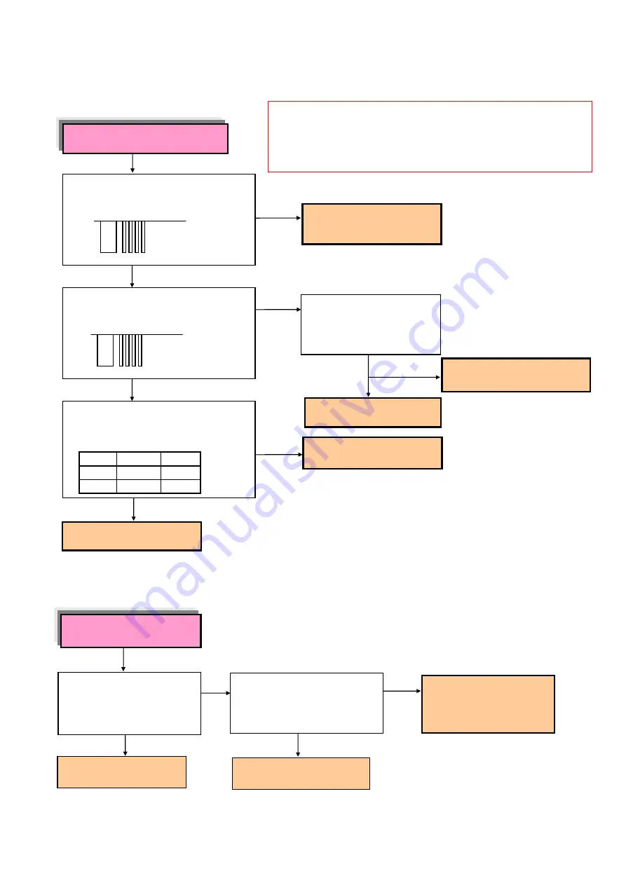
(1) The wired remote control is not effective.
When a single item is used
When a daisy chain (including the video wall) is used
Is there a signal output specified below
at Pin 7 of the RS connector?
3.3Vpp
YES
The RS232C PWB is fault.
NO
Is there a signal output specified below
at Pin 3 of the M2003? (Refer to the
PWB layout diagram on Page P4-21.)
5Vpp
YES
NO
When the RS connector is
disconnected, is there a signal output
specified below at the RS connector of
the
MAIN PWB?
Pin No. Pin name Voltage
1 M+5V
5Vdc
5 M+3.3V
3.3Vdc
NO
YES
Is there a 3.3Vdc output
at Pin 2 of the M2003?
(Refer to the PWB layout
diagram on Page P4-21.)
The remote control or the
remote control cable is fault.
YES
The RS connector or the
MAIN PWB is fault.
The 232C PWB is fault.
The 232C PWB is fault.
Are the 0Vdc and 5Vdc
outputs respectively available
at Pins 9 and 10 of the RS
connector in the standard
product of 232C PWB?
NO
The MAIN PWB is fault.
YES
The wired remote control
is not effective.
(Caution)
The wired remote control is not effective if the setting
of [PLE LINK], or [Repeat TIMER] is ON, or if the
setting of [ID NUMBER] has been made. Therefore,
such a setting should be turned off, without fail. Since
then, troubleshooting can be carried out.
NO
Check the products of
second and thereafter
according to “1 When a
single item is used.”
YES
The RS connector or the
MAIN PWB is fault.
NO
The wired remote control is not
effective.
Is there a clock signal output at
Pin 3 of the M2004? (Refer to
the PWB layout diagram on
Page P
8
-
19
.)
8-15
Summary of Contents for Elite PureVision PRO 1410HD
Page 5: ...2 3 ...
Page 6: ...2 4 ...
Page 8: ...SPECIFICATIONS PDP 614MX 3 1 ...
Page 9: ... PRO 1410HD 3 2 ...
Page 10: ...TABLE OF SIGNAL SUPPORTED PDP 614MX 4 1 ...
Page 11: ...4 2 ...
Page 12: ...4 3 PRO 1410HD ...
Page 13: ...4 4 ...
Page 14: ...PANEL FACILITIES 5 1 PDP 614MX ...
Page 15: ...5 2 ...
Page 16: ...5 3 PRO 1410HD ...
Page 17: ...5 4 ...
Page 32: ...7 11 ...
Page 44: ...All white signal All white signal 8 12 ...
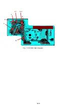
Page 50: ... Fig 1 CCD PWB Pattern Diagram A B D E 3 3V 6V C 8 18 ...
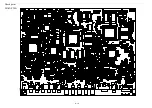
Page 51: ...8 19 Check point MAIN PWB ...
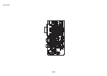
Page 52: ...8 20 232C PWB ...
Page 53: ...8 21 CLT PWB ...
Page 54: ...8 22 PWR PWB ...
Page 55: ...8 23 LED PWB ...
Page 56: ...8 24 SENB PWB ...
Page 57: ...8 25 SENC PWB ...
Page 58: ...8 26 SEND PWB ...
Page 59: ...AUDIO PWB 8 27 ...
Page 60: ...8 28 CCD PWB PX A only ...

