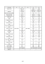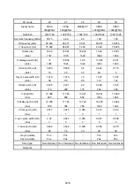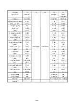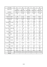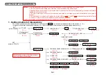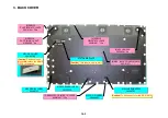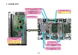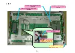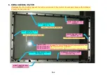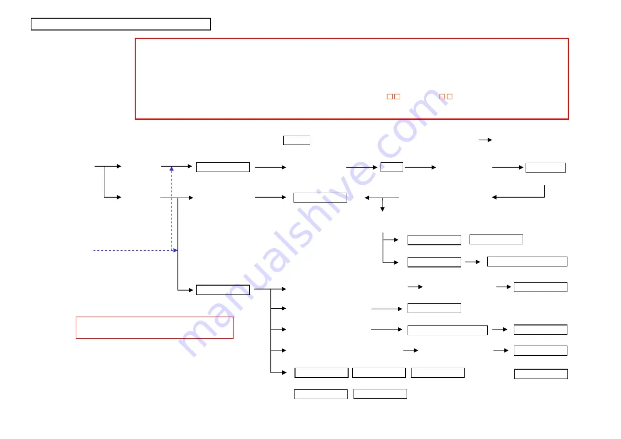
1. Outlined method of disassembly
(Caution)
1. Before disassembly, turn power off the main unit and pull out the power plug from the wall outlet.
2. Use a screwdriver with a fitting size. Otherwise, the screw threads may be damaged.
3. Reassembly can be carried out in the reverse order for disassembly. Refer to the disassembly procedures and forward
reassembly in the reverse order.
4. The order for taking out the parts (or components) is indicated by the foregoing numeral that is attached to the name of
each part.
5. The wire connector symbol is indicated by two digits of Marking . Read CN-
when examining the table of parts.
6. Class A or Class B in the text is applicable to the models specified below.
CLASS A: PX-61XM3J,61XM3A,61XM3W,61XM3G, CLASS B:
PDP-614MX,PRO-1410HD,
PX-61XR3A,61XR3W,61XR3G
SET
(with a STAND)
BACK COVER
FRONT PANEL
F-BRACKET(IN)
STAND
CHASSIS ASSY
TERMINAL PANEL M SUB ASSY
TERMINAL PANEL S
PWR PWB
232C PWB
AUDIO PWB
MAIN PWB
POWER UNIT
TERMINAL PANEL B SUB ASSY
COVER SW
PDP
FILTER
SENB PWB
SENC PWB
SEND PWB
FAN
Modifications of
a STAND
*
The outlined procedures for the disassembly of the major parts
are shown below (disassembled in the direction of
).
In regard to the details of disassembly, cautions, etc., refer to the method of replacement for each part [page indicated in ( )].
AC INLET
BACK COVER
(P
10
-2)
(P
10
-11)
(P
10
-3)
(P
10
-3)
(P
10
-4) (P
10
-5) (P
10
-6) (P
10
-6
∼
10
-7)
(P
10
-10)
Modifications of
a BACK COVER
*
(P
10
-12)
(P
10
-20)
(P
10
-13)
(P
10
-15)
(P
10
-16)
(P
10
-17)
(P
10
-14)
(P
10
-15)
(P
10
-16)
(P
10
-18)
F-BRACKET(OUT) ASSY
(P
10
-8)
LED PWB
CTL PWB
CONTROL BUTTON
COVER CTL
POWER BUTTON
(P
10
-19) (P
10
-20) (P
10
-20)
(P
10
-20)
(P
10
-18)
(P
10
-16)
(P
10
-9) (P
10
-9)
(P
10
-9) (P
10
-9)
TERMINAL PANEL B
(P
10
-18)
TERMINAL PANEL M
(P
10
-14)
F-BRACKET B(OUT)
(P
10
-9)
SET
(without a STAND)
* Modification means that the screws
are mounted or removed.
10-1
METHOD OF DISASSEMBLY
Summary of Contents for Elite PureVision PRO 1410HD
Page 5: ...2 3 ...
Page 6: ...2 4 ...
Page 8: ...SPECIFICATIONS PDP 614MX 3 1 ...
Page 9: ... PRO 1410HD 3 2 ...
Page 10: ...TABLE OF SIGNAL SUPPORTED PDP 614MX 4 1 ...
Page 11: ...4 2 ...
Page 12: ...4 3 PRO 1410HD ...
Page 13: ...4 4 ...
Page 14: ...PANEL FACILITIES 5 1 PDP 614MX ...
Page 15: ...5 2 ...
Page 16: ...5 3 PRO 1410HD ...
Page 17: ...5 4 ...
Page 32: ...7 11 ...
Page 44: ...All white signal All white signal 8 12 ...
Page 50: ... Fig 1 CCD PWB Pattern Diagram A B D E 3 3V 6V C 8 18 ...
Page 51: ...8 19 Check point MAIN PWB ...
Page 52: ...8 20 232C PWB ...
Page 53: ...8 21 CLT PWB ...
Page 54: ...8 22 PWR PWB ...
Page 55: ...8 23 LED PWB ...
Page 56: ...8 24 SENB PWB ...
Page 57: ...8 25 SENC PWB ...
Page 58: ...8 26 SEND PWB ...
Page 59: ...AUDIO PWB 8 27 ...
Page 60: ...8 28 CCD PWB PX A only ...

