69
FH-P4000,P4000R
*1)
+12dB
TRK
12
MIN
12
SEC
12
TYP
TRK MIN SEC
*2)
S. curve check setting
TRK
01
MIN
01
SEC
01
Focus Close setting
TRK
00
MIN
00
SEC
00
or
TRK
99
MIN
99
SEC
99
*8) CRG motor voltage = 2 [V]
*3)
T.Offset
Display
Switch to the order of the original display
F.Offset
Display
*7)
F.AGC
Gain
RF AGC
Gain
TRK/MIN/SEC
T.AGC
Gain
*5
Single TR
TRK
91
MIN
91
SEC
91
or
TRK
81
MIN
81
SEC
81
32TR
TRK
92
MIN
92
SEC
92
or
TRK
82
MIN
82
SEC
82
100TR
TRK
93
MIN
93
SEC
93
or
TRK
83
MIN
83
SEC
83
CRG Move
TRK
94
MIN
94
SEC
94
or
TRK
84
MIN
84
SEC
84
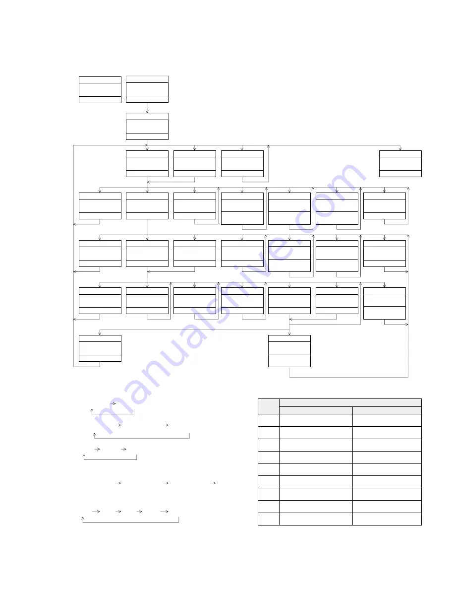
*4) 1TR/32TR/100TR
*6) Only at the time of CRG move or 100TR jump
[BAND]
Power On
(T. offset is adjusted)
TRK
00
MIN
00
SEC
00
[CD] or [SOURCE]
Source On
TRK
MIN
[4]+[6]+Reset
Test Mode In
[3]
Power On
(T. offset is not adjusted)
TRK
99
MIN
99
SEC
99
[2]
RF AMP
Gain switching
*1
TRK
GG
MIN
GG
SEC
GG
[BAND]
Power Off
TRK
MIN
SEC
[BAND]
Power Off
TRK
MIN
SEC
[BAND]
Power Off
TRK
MIN
SEC
[BAND]
Power Off
TRK
MIN
SEC
[3]
Focus Close /
S. curve check
TRK
91
MIN
91
SEC
91
[6]
Focus Mode switching
*2
TRK
0x
MIN
0x
SEC
0x
[1]
Tracking Servo
Close
TRK
00
MIN
00
SEC
00
or
TRK
99
MIN
99
SEC
99
[
[
]
CRG-
*8
TRK
00
MIN
00
SEC
00
or
TRK
99
MIN
99
SEC
99
[
]
]
CRG+
*8
TRK
00
MIN
00
SEC
00
or
TRK
99
MIN
99
SEC
99
[6]
New Test Mode
[2]
Automatic adjustment value
display switching
*3
TRK
??
MIN
??
SEC
??
[1]
T.CLS and F,T AGC
and RF AGC and
Applicable servomechanism
TRK
xx
MIN
xx
SEC
xx
[6]
T.Close and
Applicable servomechanism
TRK
xx
MIN
xx
SEC
xx
[3]
RF AGC /
RF AGC coefficient display
TRK
??
MIN
??
SEC
??
[
]
]
CRG+
TRK
8x
MIN
8x
SEC
8x
or
TRK
9x
MIN
9x
SEC
9x
[
[
]
CRG-
TRK
8x
MIN
8x
SEC
8x
or
TRK
9x
MIN
9x
SEC
9x
[2]
T.Balance adjustment /
T.Balance coefficient display
TRK
??
MIN
??
SEC
??
[1]
F,T,RF AGC /
F.Bias display switching
*7
TRK
??
MIN
??
SEC
??
[3]
F,T AGC,F.Bias
and RF AGC
TRK
xx
MIN
xx
SEC
xx
[6]
CRG/TR jump value
*5
switching
TRK
xx
MIN
xx
SEC
xx
[
]
]
CRG+/TR Jump+
*4
TRK
xx
MIN
xx
SEC
xx
[
[
]
CRG-/TR Jump-
*4
TRK
xx
MIN
xx
SEC
xx
[2]
Tracking Open
TRK
8x
MIN
8x
SEC
8x
or
TRK
9x
MIN
9x
SEC
9x
[2]
Tracking Open
TRK
8x
MIN
8x
SEC
8x
or
TRK
9x
MIN
9x
SEC
9x
F. EQ measurement setting
TRK
02
MIN
02
SEC
02
[Key]
[BAND]
[
]
]
[
[
]
[1]
[2]
[3]
[6]
-
-
Power On/Off
CRG +/TR Jump+
(Direction of the external surface)
CRG -/TR Jump-
(Direction of the internal surface)
T.CLS and AGC and Applicable servomechanism/
AGC,AGC display switching
RF Gain switching/Offset adjustment display/
T.Balance adjustment/T.OPN
F.CLS,S.Curve/Rough Servo and RF AGC/
F,T,RF AGC
SPDL 1X/2X switching
(Double-speed compatibility only)
Error rate measurement
F.Mode switching/T.CLS/CRG,TR
Jump switching
Test Mode
New Test Mode
Operation
Error occurrence time/
cause display switching
TRK+/FF
TRK-/REV
SCAN
MODE
(ITP)
-
-
Auto/Manual switching
F.Bias
[KEY]
Contents
Display
-
Flow Chart
Summary of Contents for FH-P4000
Page 12: ...12 FH P4000 P4000R 2 5 CD MECHANISM MODULE C ...
Page 14: ...14 FH P4000 P4000R 2 6 CASSETTE MECHANISM MODULE E D ...
Page 31: ...31 FH P4000 P4000R 5 6 7 8 5 6 7 8 D C B A 47K B KEYBOARD UNIT A CN801 B ...
Page 32: ...32 FH P4000 P4000R 1 2 3 4 1 2 3 4 D C B A 3 5 KEYBOARD UNIT FH P4000R X1N EW PE5234B A B ...
Page 33: ...33 FH P4000 P4000R 5 6 7 8 5 6 7 8 D C B A 47K B KEYBOARD UNIT A CN801 B ...
Page 42: ...IC Q A AUDIO AMP UNIT A 42 FH P4000 P4000R 1 2 3 4 1 2 3 4 D C B A ...
Page 43: ...A FRONT 43 FH P4000 P4000R 5 6 7 8 5 6 7 8 D C B A SIDE B ...
Page 45: ...45 FH P4000 P4000R 1 2 3 4 1 2 3 4 D C B A IC Q KEYBOARD UNIT B B CN801 A SIDE B ...
Page 47: ...47 FH P4000 P4000R 1 2 3 4 1 2 3 4 D C B A SIDE B CONTROL UNIT C C CLAMP 8EJ ...
Page 71: ...71 FH P4000 P4000R Grating waveform Ech Xch 20mV div AC Fch Ych 20mV div AC 45 0 75 60 30 90 ...


