79
FH-P4000,P4000R
-
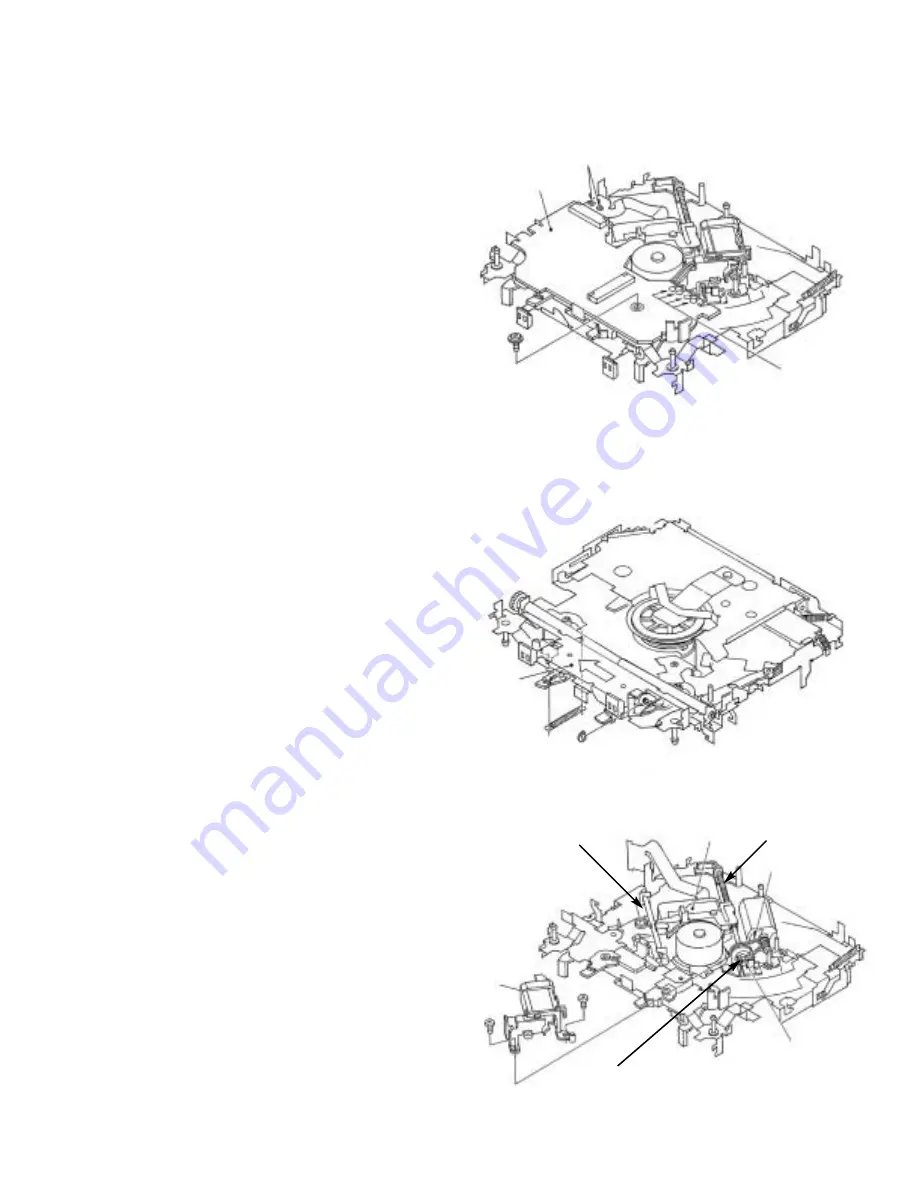
How to remove the Control Unit
1. Give jumper-solder treatment to the Flexible Wire of
the Pickup unit, then remove the wire from the
Connector.
2. Remove all 4 points of solder-treatment on the Lead
Wire. Also, unscrew the screw(1 piece).
3. Then, Remove the Control unit.
(Caution)
Be careful not to damage SW when you reassemble
the Control Unit into the device.
-
How to remove the Loading Arm Assy
1. Unlock the spring (1 piece) and remove the E ring (1
piece) of the Fulcrum Shaft.
2. Shift the arm to the left side direction and unlock pins
(2 pieces).
-
How to remove the Pickup Unit
1. Unscrew 2 pieces of screws, then remove the Pulley
Cover.
2. Remove the Feed Screw unit from the pawl of the
Feed Screw Guide (The pawl is located inside the
guide).
3. Remove the belt from the Pulley, then remove the
Pickup unit.
(Caution)
Make sure not to stain the belt with grease when you
fix the belt.
Control Unit
Jumper-Solder
Solder
Loading Arm Assy
Pickup Unit
Pulley Cover
Feed Screw Guide
Belt
Grease Application
Grease Application
Grease Application
Summary of Contents for FH-P4000
Page 12: ...12 FH P4000 P4000R 2 5 CD MECHANISM MODULE C ...
Page 14: ...14 FH P4000 P4000R 2 6 CASSETTE MECHANISM MODULE E D ...
Page 31: ...31 FH P4000 P4000R 5 6 7 8 5 6 7 8 D C B A 47K B KEYBOARD UNIT A CN801 B ...
Page 32: ...32 FH P4000 P4000R 1 2 3 4 1 2 3 4 D C B A 3 5 KEYBOARD UNIT FH P4000R X1N EW PE5234B A B ...
Page 33: ...33 FH P4000 P4000R 5 6 7 8 5 6 7 8 D C B A 47K B KEYBOARD UNIT A CN801 B ...
Page 42: ...IC Q A AUDIO AMP UNIT A 42 FH P4000 P4000R 1 2 3 4 1 2 3 4 D C B A ...
Page 43: ...A FRONT 43 FH P4000 P4000R 5 6 7 8 5 6 7 8 D C B A SIDE B ...
Page 45: ...45 FH P4000 P4000R 1 2 3 4 1 2 3 4 D C B A IC Q KEYBOARD UNIT B B CN801 A SIDE B ...
Page 47: ...47 FH P4000 P4000R 1 2 3 4 1 2 3 4 D C B A SIDE B CONTROL UNIT C C CLAMP 8EJ ...
Page 71: ...71 FH P4000 P4000R Grating waveform Ech Xch 20mV div AC Fch Ych 20mV div AC 45 0 75 60 30 90 ...

