84
FH-P4000,P4000R
-
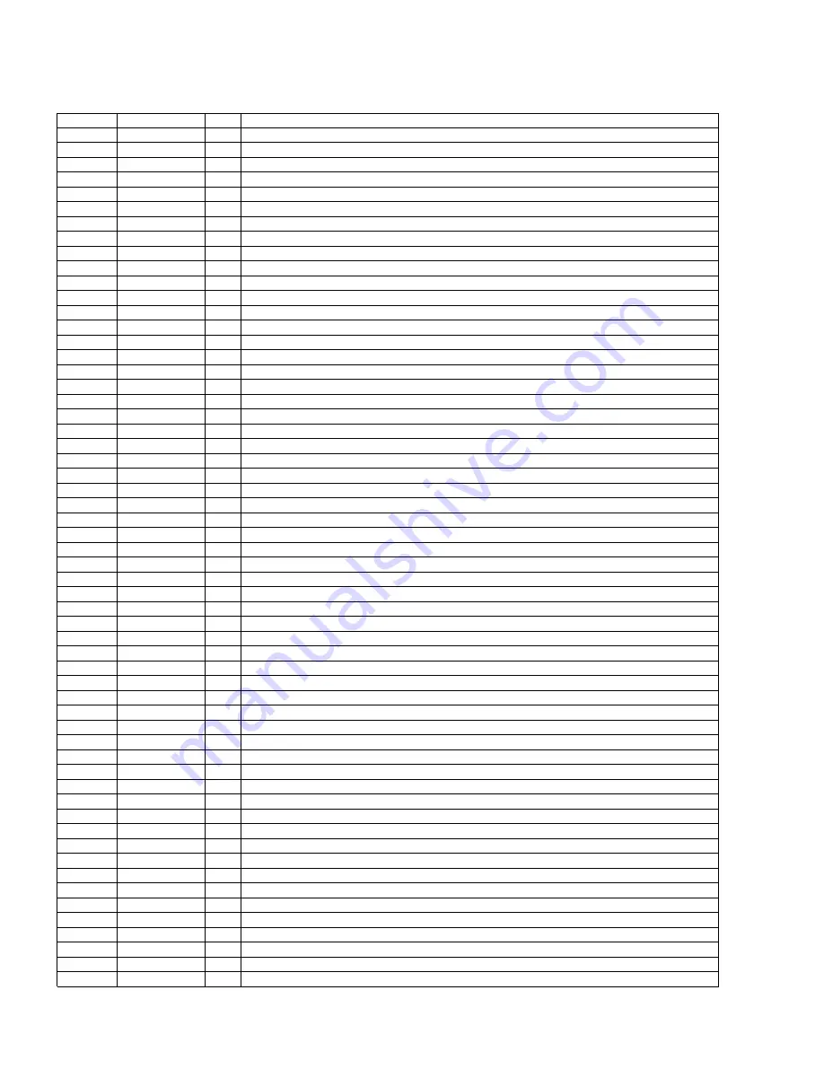
Pin Functions (PE5211A)
Pin No.
Pin Name
I/O
Function and Operation
1
ST
I
TUN:stereo input
2
SD
I
TUN:SD input
3
NC
Not used
4
LOCH
O
TUN:Local H output
5
LOCL
O
TUN:Local L output
6-8
NC
Not used
9
RESET
I
System reset input
10
X2
Crystal oscillator connection pin
11
X1
Crystal oscillator connection pin
12
VSS
PLL:Regulator grand potential
13
REGC1
PLL:Capacitor for regulator connect pin
14
VDD
Power supply
15
REGC0
Capacitor for regulator connect pin
16
VSS
Regulator grand potential
17
NC
Not used
18
XT1
Clock terminal
19
CKSEL
I
PLL mode:three times select input
20-24
NC
Not used
25
CD5VON
O
CD:+5V power supply control output
26
BKLT
O
Back light output
27
VDSEL
O
VD voltage select control output
28
VPP
Voltage for Program
29–32
NC
Not used
33
VST
O
E-VOL:Strobe pulse output
34
VCK
O
E-VOL:Clock output
35
VDT
O
E-VOL:Data output
36
DIMMER
O
DIMMER select output
37,38
NC
Not used
39
DSPERR2
O
DSP:Error detect output
40
DSPCS
O
DSP:Chip select output
41
DSPRST
O
DSP:Reset control output
42
DSPERR1
O
DSP:Error detect output
43
DSPACK
O
DSP:IC ready output
44
IFOK
I
IF signal input
45
ROMCS
O
ROM correction chip select output
46
ROMCLK
O
ROM correction clock output
47
ROMDATA
I/O
ROM correction data input/output
48–53
NC
Not used
54
HOME
I
CD:CRG home position detector input
55
CONT
O
CD:Servo driver power supply control output
56
VDCONT
O
CD:VD power control output
57
NC
Not used
58
LOEJ
O
CD:Load/Eject direction change output
59
CLCNT
O
CD:Driver input select output
60
NC
Not used
61
VSS
GND
62
VDD
Power supply
63
MSIN
O
3L:MS sense output
64
DIRO
O
3L:Head N/R select output
65
PLAY
O
3L:MS gain select output
66
MTLSW
O
3L:Metal sense output
67
NR
O
3L:Noise reduction output
68
LOADSW
I
3L:Loading SW input
69
POS
O
3L:Position sense output
70
RES
I
3L:Reverse sense input
71
NES
I
3L:Normal sense input
72
SC2
I
3L:Sub motor control input 2
73
SC1
I
3L:Sub motor control input 1
Summary of Contents for FH-P4000
Page 12: ...12 FH P4000 P4000R 2 5 CD MECHANISM MODULE C ...
Page 14: ...14 FH P4000 P4000R 2 6 CASSETTE MECHANISM MODULE E D ...
Page 31: ...31 FH P4000 P4000R 5 6 7 8 5 6 7 8 D C B A 47K B KEYBOARD UNIT A CN801 B ...
Page 32: ...32 FH P4000 P4000R 1 2 3 4 1 2 3 4 D C B A 3 5 KEYBOARD UNIT FH P4000R X1N EW PE5234B A B ...
Page 33: ...33 FH P4000 P4000R 5 6 7 8 5 6 7 8 D C B A 47K B KEYBOARD UNIT A CN801 B ...
Page 42: ...IC Q A AUDIO AMP UNIT A 42 FH P4000 P4000R 1 2 3 4 1 2 3 4 D C B A ...
Page 43: ...A FRONT 43 FH P4000 P4000R 5 6 7 8 5 6 7 8 D C B A SIDE B ...
Page 45: ...45 FH P4000 P4000R 1 2 3 4 1 2 3 4 D C B A IC Q KEYBOARD UNIT B B CN801 A SIDE B ...
Page 47: ...47 FH P4000 P4000R 1 2 3 4 1 2 3 4 D C B A SIDE B CONTROL UNIT C C CLAMP 8EJ ...
Page 71: ...71 FH P4000 P4000R Grating waveform Ech Xch 20mV div AC Fch Ych 20mV div AC 45 0 75 60 30 90 ...


