76
FH-P4000,P4000R
-
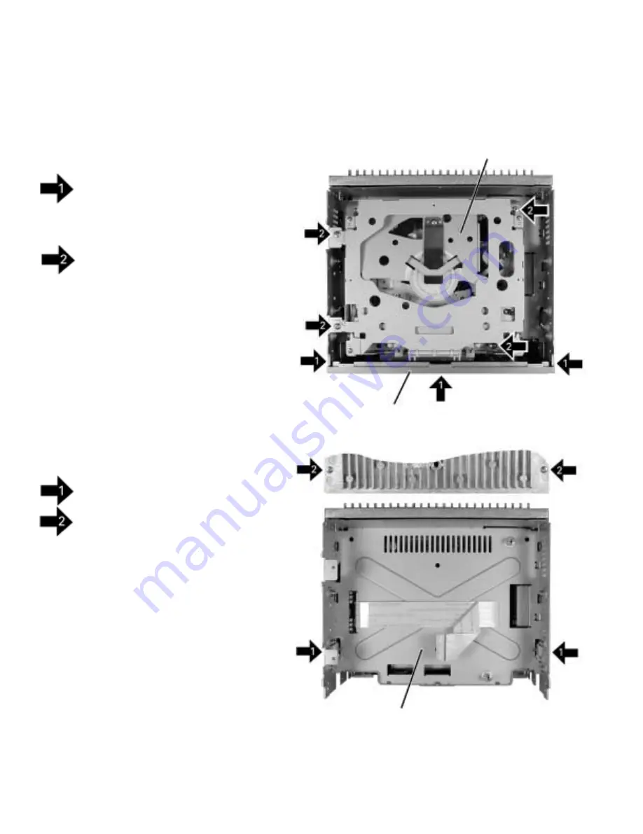
Removing the Chassis Unit (Fig.2)
Remove the two screws.
Remove the two screws and then remove the
Chassis Unit.
-
Removing the Case (not shown)
1. Remove the Case.
-
Removing the Panel Assy (Fig.1)
Remove the three screws and then remove the
Panel Assy.
-
Removing the CD Mechanism Module (Fig.1)
Remove the four screws.
Disconnect the connector and then remove the CD
Mechanism Module.
Note : Remove or tighten the screw A with supporting
the Chassis Unit by your hand from underneath.
Tighten the screws by turns started from A.
Fig.1
7.1.2 DISASSEMBLY
Fig.2
Chassis Unit
CD Mechanism Module
Panel Assy
A
B
C
D
Summary of Contents for FH-P4000
Page 12: ...12 FH P4000 P4000R 2 5 CD MECHANISM MODULE C ...
Page 14: ...14 FH P4000 P4000R 2 6 CASSETTE MECHANISM MODULE E D ...
Page 31: ...31 FH P4000 P4000R 5 6 7 8 5 6 7 8 D C B A 47K B KEYBOARD UNIT A CN801 B ...
Page 32: ...32 FH P4000 P4000R 1 2 3 4 1 2 3 4 D C B A 3 5 KEYBOARD UNIT FH P4000R X1N EW PE5234B A B ...
Page 33: ...33 FH P4000 P4000R 5 6 7 8 5 6 7 8 D C B A 47K B KEYBOARD UNIT A CN801 B ...
Page 42: ...IC Q A AUDIO AMP UNIT A 42 FH P4000 P4000R 1 2 3 4 1 2 3 4 D C B A ...
Page 43: ...A FRONT 43 FH P4000 P4000R 5 6 7 8 5 6 7 8 D C B A SIDE B ...
Page 45: ...45 FH P4000 P4000R 1 2 3 4 1 2 3 4 D C B A IC Q KEYBOARD UNIT B B CN801 A SIDE B ...
Page 47: ...47 FH P4000 P4000R 1 2 3 4 1 2 3 4 D C B A SIDE B CONTROL UNIT C C CLAMP 8EJ ...
Page 71: ...71 FH P4000 P4000R Grating waveform Ech Xch 20mV div AC Fch Ych 20mV div AC 45 0 75 60 30 90 ...

