background image

FH-P800BT/XJ/UC

74

1

2

3

4

1

2

3

4

C

D

F

A

B

E

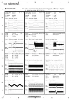
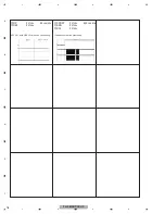
10.5  WAVEFORMS

-

 CD CORE UNIT

Note : 1. The encircled numbers denote measuring points in the circuit diagram.

2. Reference voltage  REFO1(1.65 V)

500 ms/div

5 V/div
5 V/div
5 V/div
10 V/div

1

DSCSNS

5

CLCONT

4

LOEJ

6

VD

5 V/div
5 V/div
5 V/div
5 V/div

1

DSCSNS

2

8SNS

3

12SNS

4

LOEJ

5 V/div
5 V/div
5 V/div
5 V/div

500 ms/div

1

DSCSNS

2

8SNS

3

12SNS

4

LOEJ

500 mV/div
500 mV/div

200 ms/div

@

TE

#

FE

200 mV/div
2 V/div
2 V/div

500 ms/div

0

FIN

!

RFOK(MONI_3)

7

SIN

1 V/div
500 mV/div
1 V/div

1 s/div

500 ms/div

7

SIN

8

CIN

9

TIN

2 V/div
500 mV/div

μ

s/div

$

MDX

7

SIN

2 V/div
500 mV/div

200 ms/div

$

MDX

7

SIN

500 mV/div
500 mV/div
500 mV/div
500 mV/div

20 ms/div

#

FE

0

FIN

@

TE

9

TIN

1 V/div
500 mV/div
500 mV/div

500 

μ

s/div

%

RFAGC

@

TE

9

TIN

500 mV/div
500 mV/div

2 ms/div

@

TE

%

RFAGC

500 mV/div
500 mV/div

200 ms/div

0

FIN

#

FE

Source On setup operation

12 cm CD-DA Source On setup operation

CD-DA Play operation

Spindle waveform during play operation

Spindle waveform during play operation
(Wider)

Focus Search waveform

Track Open waveform

1 Track Jump waveform

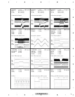
12 cm CD-DA setup operation after loading

12 cm CD Loading operation

12 cm CD Loading operation

8 cm CD Loading operation

Ref.:
GND

Mode:
Normal

Ref.:
GND

Mode:
Normal

Ref.:
GND

Mode:
Normal

Ref.:
REFO

Mode:
Normal

Ref.:
REFO

Mode:
Normal

Ref.:
REFO

Mode:
Normal

Ref.:
REFO

Mode:
TEST

Ref.:
REFO

Mode:
TEST

Ref.:
REFO

Mode:
TEST

Ref.:
REFO

Mode:
Normal

Ref.:
REFO

Mode:
Normal

Ref.:
REFO

Mode:
Normal

Summary of Contents for FH-P6050UB

Page 1: ...ore 159936 PIONEER CORPORATION 2008 FH P800BT XJ UC CRT4134 CD RECEIVER FH P800BT XJ UC FH P8000BT XJ UC CD RDS RECEIVER FH P80BT XJ EW5 CD RECEIVER FH P6050UB XJ ES This service manual should be used together with the following manual s Model No Order No Mech Module Remarks CX 3240 CRT4050 S10 5COMP2 iPod USB CD Mech Module Circuit Descriptions Mech Descriptions Disassembly For details refer to I...

Page 2: ...ced only by the component specified in that documentation for safety reasons the following symbol shall be used CAUTION This service manual is intended for qualified service technicians it is not meant for the casual do it yourselfer Qualified technicians have the necessary test equipment and tools and have been trained to properly and safely repair complex products such as those covered by this m...

Page 3: ...e laser component is capable of emitting radiation exceeding the limit for CLASS 1 A specially instructed person should do servicing operation of the apparatus Laser diode characteristics Wave length 785 nm to 814 nm Maximum output 1 190 W Emitting period unlimited Additional Laser Caution Transistors Q101 in PCB drive the laser diodes When Q101 is shorted between their terminals the laser diodes ...

Page 4: ...de the product Please check that neither solder debris nor screws remain inside the product 8 There should be no semi broken wires scratches melting etc on the coating of the power cord Damaged power cords may lead to fire accidents so please be sure that there are no damages If you find a damaged power cord please exchange it with a suitable one 9 There should be no spark traces or similar marks ...

Page 5: ...ON 29 6 SERVICE MODE 30 6 1 CD TEST MODE 30 6 2 DISPLAY TEST MODE 32 6 3 BLUETOOTH TEST MODE 33 7 DISASSEMBLY 37 8 EACH SETTING AND ADJUSTMENT 42 8 1 CHECKING THE GRATING AFTER CHANGING THE PICKUP UNIT 42 8 2 PCL OUTPUT CONFIRMATION 44 9 EXPLODED VIEWS AND PARTS LIST 46 9 1 PACKING 46 9 2 EXTERIOR 1 50 9 3 EXTERIOR 2 54 9 4 CD MECHANISM MODULE 56 10 SCHEMATIC DIAGRAM 58 10 1 OVERALL CONNECTION DIA...

Page 6: ...2 iPod C2 mechanism When you install the S10 5COMP2 USB mechanism by mistake It becomes the following error display by the CDS USB source C H K C D C O R E For environmental protection lead free solder is used on the printed circuit boards mounted in this unit Be sure to use lead free solder and a soldering iron that can meet specifications for use with lead free solders for repairs accompanied by...

Page 7: ...FH P800BT XJ UC 7 5 6 7 8 5 6 7 8 C D F A B E 2 SPECIFICATIONS 2 1 SPECIFICATIONS ...

Page 8: ...FH P800BT XJ UC 8 1 2 3 4 1 2 3 4 C D F A B E ...

Page 9: ...D F A B E 2 2 DISC CONTENT FORMAT The Bluetooth word mark and logos are owned by the Bluetooth SIG Inc and any use of such marks by Pioneer Corporation is under license Other trademarks and trade names are those of their respective owners ...

Page 10: ...FH P800BT XJ UC 10 1 2 3 4 1 2 3 4 C D F A B E 2 3 PANEL FACILITIES FH P800BT XJ UC FH P8000BT XJ UC FH P80BT XJ EW5 ...

Page 11: ...FH P800BT XJ UC 11 5 6 7 8 5 6 7 8 C D F A B E FH P800BT XJ UC FH P8000BT XJ UC FH P80BT XJ EW5 ...

Page 12: ...FH P800BT XJ UC 12 1 2 3 4 1 2 3 4 C D F A B E FH P800BT XJ UC FH P8000BT XJ UC FH P80BT XJ EW5 ...

Page 13: ...FH P800BT XJ UC 13 5 6 7 8 5 6 7 8 C D F A B E FH P6050UB XJ ES ...

Page 14: ...FH P800BT XJ UC 14 1 2 3 4 1 2 3 4 C D F A B E FH P6050UB XJ ES ...

Page 15: ...FH P800BT XJ UC 15 5 6 7 8 5 6 7 8 C D F A B E FH P6050UB XJ ES ...

Page 16: ...FH P800BT XJ UC 16 1 2 3 4 1 2 3 4 C D F A B E 2 4 CONNECTION DIAGRAM FH P800BT XJ UC ...

Page 17: ...FH P800BT XJ UC 17 5 6 7 8 5 6 7 8 C D F A B E FH P8000BT XJ UC ...

Page 18: ...FH P800BT XJ UC 18 1 2 3 4 1 2 3 4 C D F A B E FH P80BT XJ EW5 ...

Page 19: ...FH P800BT XJ UC 19 5 6 7 8 5 6 7 8 C D F A B E FH P6050UB XJ ES ...

Page 20: ...must be normal 2 CD Play back a CD Track search No malfunction on display audio and operation Display audio and operations must be normal 3 FM AM tuner Check FM AM tuner action Seek Preset Switch band to check both FM and AM Display audio and operations must be normal 4 Check whether no disc is inside the product The media used for the operating check must be ejected 5 Appearance check No scratche...

Page 21: ...9 FH P800BT XJ UC Unit Number CZW5570 FH P8000BT XJ UC Unit Number CZW5568 FH P80BT XJ EW5 Unit Name Combi PWB Unit Unit Number CZW5571 FH P6050UB XJ ES Unit Name Comb PWB Unit Unit Number CZW5574 UC Unit Number CZW5573 EW5 Unit Number CZW5575 ES Unit Name Keyboard Unit Unit Number CWN3394 UC EW5 Unit Name Bluetooth Unit Unit Number CWX3624 Unit Name CD Core Unit S10 5COMP2 iPod C2 ...

Page 22: ...ating Two pieces Removing the cord assy BT antenna cable Grease List Name Grease Grease Grease No GEM1024 GEM1045 Remarks CD Mechanism Module CD Mechanism Module Before shipping out the product be sure to clean the following portions by using the prescribed cleaning tools Portions to be cleaned Cleaning tools CD pickup lenses Cleaning liquid GEM1004 Cleaning paper GED 008 ...

Page 23: ...FH P800BT XJ UC 23 5 6 7 8 5 6 7 8 C D F A B E ...

Page 24: ...YNC FLG EN VIN VOUT FB SW INV B U JA290 VD B U Q701 36 38 37 OEL15V Q301 IP BUS ASLIN 93 EMUTE 23 SACLK 59 SAOUT 90 A B A B C D PEG437A PEG436A PEG438A FH P800BT XJ UC FH P8000BT XJ UC FH P80BT XJ EW5 FH P6050UB XJ ES A B C D RESET CN1 FMRF ANT adj RF adj FM ANT T51 CF52 RFGND VDD_3 3 OSCGND DGND AUDIOGND NC VCC 3 3V 2 5V IC 4 3 3V 2 5V IC 2 2 5V NC CE2 ROM_VDD SL DI CK CE1 LDET DO RDS_CK RDS_DATA...

Page 25: ... 7 9 16 6 15 JA600 AUX SL TUNPCE1 TUNPDO TUNPDI 95 69 24 70 47 46 TUNPCK 48 CE1 DO DI CK Q651 KEYD 2 KEYAD 89 Q852 RL FL SWL RL FL SWL FL SWL INDTEL JA450 RCA OUT RL RL FL FL GND B REM TUNPCE2 CE2 VOL SW2 EVOL SW1 B U 1 1 3 2 6 1 IC660 NJM2388F84 B REM CONT IC510 TPD1018F IC670 NJM2885DL1 33 4 SL RCK 16 RDS_CK RDSLK 82 RDS_LOCK RDS57K 83 RDS_DATA RDT 84 RDS_HSLK LDET 17 LDET BT_3V 10 5 1 2 1 3 45 ...

Page 26: ... L H Pin 38 Source keys operative Completes power on operation After that proceed to each source operation SYSPW H Pin 1 ASENBO H Pin 80 Starts communication with Grille microcomputer Source ON 500 ms 500 ms In case of the above signal the communication with Grille microcomputer may fail If the time interval is not 500 msec the oscillator may be defective ...

Page 27: ...tch or CRG move mechanism Communication error between microcomputer and SERVO LSI 11 Electricity Focus Servo NG Focusing not available Stains on rear side of disc or excessive vibrations on REWRITABLE 12 Electricity Spindle Lock NG Spindle not locked Sub code is strange not readable Subcode NG Failure on spindle stains or damages on disc or excessive vibrations A disc not containing CD R data is f...

Page 28: ...FH P800BT XJ UC 28 1 2 3 4 1 2 3 4 C D F A B E ...

Page 29: ...9 5 6 7 8 5 6 7 8 C D F A B E 5 3 CONNECTOR FUNCTION DESCRIPTION FRONT REAR R L SW FUSE 10A M4X8 MAX ANTENNA JACK FRONT OUTPUT UC EW5 REAR OUTPUT SUBWOOFER OUTPUT USB AUX JACK WIRED REMOTE INPUT UC EW5 MIC INPUT UC EW5 ...

Page 30: ...tections will not work Avoid applying any mechanical or electrical shock to the mechanism during adjustment The RFI and RFO signals with a wide frequency range are easy to oscillate When observing the signals insert a resistor of 1k ohms in series The load and eject operation is not guarantied with the mechanism upside down If the mechanism is blocked due to mistaken eject operation reset the prod...

Page 31: ...X switching As for the double speed 2x audio output cannot be supported 5 Error Rate measurement ON ERR 30 Counts Start BER display data 6 F Mode switching Tracking Close CRG TR Jump Switching As for the double speed 2x audio output cannot be supported After the Eject key is pressed keys other than the Eject key should not be pressed until disc ejection is complete When the key 2 or 3 is pressed d...

Page 32: ...m version is displayed the PD number the system microcomputer version and the CWW number is displayed Example For PEG123A VER1 02 CWW1111 The ACC and back up turn off and turn on while pushing the key Usual display test mode display Display test mode all lighting Display STOP ROM Correction version display Ver1 02 System version display Ver1 02 1 2 3 A 1 0 2 C 1 1 1 1 DISP MUTE DISP MUTE DISP MUTE...

Page 33: ...ect messages ap pear on the display Press RESET with a pen tip or other pointed instrument 1 Press SOURCE and hold until the unit turns off 2 Press MULTI CONTROL and hold until the initial setting menu appears in the display 3 Turn MULTI CONTROL to select of BT RESET MEMORY 4 Push MULTI CONTROL right to show a confirmation display BT RESET YES is displayed Clearing memory is now on standby If you ...

Page 34: ...already registered among available No 1 through 3 for registration take note that the telephone information having registered by user will be overwritten 2 Outline of Functions The following 2 items are to be confirmed for the simple BT action check by using BT compliant mobile phone Confirmation of Bluetooth connection certification connection and voice connection Confirmation of BT antenna sensi...

Page 35: ...t must be directly connected to the cable A gray coaxial cable connected to the antenna connector on BT unit is removed by taking out the upper case and CD mechanics of the product This task would be safer if a special connector drawing jig is available Next the U FL connector from spectrum analyzer is connected The styling of cable must be taken good care so as not to add further burden on BT ant...

Page 36: ...r key and select frequency Initial value is 2 402 MHz Select frequency by Up Down keys Initial value is 2 402 MHz 02 2402 41 2441 80 2480 Determine by Center key Screen displaying LOCAL TX NM Setup Defined This is the end of product setup L O O P B A C K Determine the output level of each frequency by spectrum analyzer upon the above connection The output level V must be within the range of the fo...

Page 37: ...w Fig 3 Keyboard Unit Knob Unit Removing the CD Mechanism Module Fig 4 CD Mechanism Module Disconnect the cable and then remove the CD Mechanism Module Remove the ten screws and then remove the Keyboard Unit Fig 3 1 Fig 4 Cace Grille Assy 2 Detach the four hooks on tip of white arrows and then remove the Grille Assy Knob Unit Remove the Knob Unit Fig 2 Remove the four screws 1 1 1 1 1 1 1 1 1 1 1 ...

Page 38: ...f connector How to Attach the Cord Assy For inserting cord assy adjust cord assy with the engagement axis of connector and insert it as vertically as possible Do not insert the cord assy in extreme slant as the connector might suffer damage Connector Cord Assy GGF1539 Removing the Cace Unit Fig 5 6 Fig 5 Fig 6 Remove the two screws Fig 5 Removing the Antenna Unit Fig 7 Fig 7 1 1 1 2 2 2 2 2 Remove...

Page 39: ... B E Removing the Combi PWB Unit Fig 8 9 Remove the two screw Fig 8 3 Remove the two screws and the remove Heatsink Fig 8 1 2 Combi PWB Unit Remove the seven screws and then remove Combi PWB Unit Fig 9 Fig 9 Heatsink Fig 8 2 1 1 2 3 3 3 3 3 3 3 ...

Page 40: ...he mechanism remove the two Springs A the six Springs B and the four Screws 2 Turn the Upper Frame using the part a as a pivot and remove the Upper Frame 3 While lifting the Carriage Mechanism remove it from the three Dampers Caution When assembling be sure to apply some alcohol to the Dampers and assemble the mechanism in a clamped state 1 Hold the Upper and Lower Frames 2 Do not hold the front p...

Page 41: ...up Lock Arm Feed Screw Inner Holder Planet Gear How to remove the Pickup Unit 1 Make the system in the carriage mechanism mode and have it clamped 2 Remove the CD Core Unit and remove the leads from the Inner Holder 3 Remove the Poly Washer Change Arm and Pickup Lock Arm 4 While releasing from the hook of the Inner Holder lift the end of the Feed Screw Caution When assembling move the Planet Gear ...

Page 42: ...ad the disc and switch the 3 V regulator on 2 Using the and buttons move the PU unit to the innermost track 3 Press key 3 to close focus the display should read 91 Press key 2 to implement the tracking balance adjustment the display should now read 81 Press key 3 The display will change returning to 81 on the fourth press 4 As shown in the diagram above monitor the LPF outputs using the oscillosco...

Page 43: ...FH P800BT XJ UC 43 5 6 7 8 5 6 7 8 C D F A B E Grating waveform 45 degrees 0 degrees 75 degrees 60 degrees 30 degrees 90 degrees Ech Xch 20 mV div AC Fch Ych 20 mV div AC ...

Page 44: ...rmal operation mode with the detachable panel installed the ACC switched ON the standby mode cancelled shift the TESTIN IC1 Pin 86 terminal to H The clock signal is output from the PCL terminal IC1 Pin 41 The frequency of the clock signal is 625 0 kHz that is one 32th of the fundamental frequency ...

Page 45: ...FH P800BT XJ UC 45 5 6 7 8 5 6 7 8 C D F A B E ...

Page 46: ...st The mark found on some component parts indicates the importance of the safety factor of the part Therefore when replacing be sure to use parts of identical designation Screw adjacent to mark on the product are used for disassembly For the applying amount of lubricants or glue follow the instructions in this manual In the case of no amount instructions apply as you think it appropriate ...

Page 47: ...885 Remote Control Assy 11 Cord Assy CZD5514 CZD5514 CZD5513 CZD5514 12 Screw Assy CZE2982 CZE2982 Not used CZE2982 13 Screw BMZ50P080FTC BMZ50P080FTC Not used BMZ50P080FTC 14 Screw CMZ50P080FTC CMZ50P080FTC Not used CMZ50P080FTC 15 Polyethylene Bag CZE2983 CZE2983 Not used CZE2983 16 Cushion CZH6667 CZH6667 CZH6665 CZH6667 17 Cushion CZH6668 CZH6668 CZH6666 CZH6668 18 Unit Box CZH6669 CZH6671 CZH...

Page 48: ... CZR5529 Italian CZR5530 Dutch CZR5531 Russian CZR5534 Portuguese B CZR5535 Traditional Chinese CZR5536 Arabic Mark FH P800BT XJ UC CZR5517 FH P8000BT XJ UC CZR5511 FH P80BT XJ EW5 CZR5520 FH P6050UB XJ ES CZR5514 Language CRB2770 CRB2776 CRB2756 CRB2782 English CRB2772 CRB2778 CRB2757 CRB2783 Spanish CRB2771 CRB2777 CRB2759 French CRB2758 German CRB2760 Italian CRB2761 Dutch CRB2762 Russian CRB27...

Page 49: ...FH P800BT XJ UC 49 5 6 7 8 5 6 7 8 C D F A B E ...

Page 50: ...FH P800BT XJ UC 50 1 2 3 4 1 2 3 4 C D F A B E 9 2 EXTERIOR 1 A A D E A A ...

Page 51: ...Contrast table 2 38 Top Cover CZN8397 39 Sheet See Contrast table 2 40 Plate CZN8407 41 42 Cushion CZN8409 43 Heat Sink CZN8384 44 Combi PWB Unit See Contrast table 2 45 Screw BMZ26P180FTB 46 47 Screw BSZ26P080FTC 48 Screw BSZ26P140FTC 49 Fuse 10 A CEK1208 50 Plug CN80 CKS3538 51 Connector CN300 See Contrast table 2 52 Connector CN800 See Contrast table 2 53 54 55 FM AM Tuner Unit See Contrast tab...

Page 52: ...4822 CKS4822 CKS4822 Not used 52 Connector CN800 CKS5321 CKS5321 CKS5321 Not used 55 FM AM Tuner Unit CWE2098 CWE2098 CWE2097 CWE2098 58 Bluetooth Unit CWN3394 CWN3394 CWN3394 Not used 59 Connector CN79 CKS5320 CKS5320 CKS5320 Not used 60 Connector CN1 CKS5749 CKS5749 CKS5749 Not used 61 Shield CND3134 CND3134 CND3134 Not used 62 Sheet CNM9598 CNM9598 CNM9598 Not used 63 Bluetooth Module Y1 CWX361...

Page 53: ...FH P800BT XJ UC 53 5 6 7 8 5 6 7 8 C D F A B E ...

Page 54: ...FH P800BT XJ UC 54 1 2 3 4 1 2 3 4 C D F A B E 9 3 EXTERIOR 2 B ...

Page 55: ... Unit CZX6626 17 Case CZN8378 18 Holder CZN8377 19 Insulator CZN8410 20 Tape CZN8399 21 OEL Module MXS8252 22 Remote Control Unit See Contrast table 2 23 Cover See Contrast table 2 24 Cushion CZN8379 25 IC IC901 GP1UX51RX 26 Hinge Unit CZX6625 27 Keyboard Unit See Contrast table 2 28 Case Unit CZX6631 Mark No Description Part No Mark No Description FH P800BT XJ UC FH P8000BT XJ UC FH P80BT XJ EW5 ...

Page 56: ...9 13 13 66 44 44 72 8 15 60 46 33 62 38 39 40 28 4 47 17 37 14 12 35 6 45 52 53 65 64 18 32 41 5 61 49 8 51 55 51 56 59 43 10 20 57 16 25 58 31 23 69 71 70 70 63 73 21 7 19 24 19 24 67 4 36 68 50 1 1 1 1 1 1 1 E 30 34 22 42 11 26 1 1 1 1 1 1 1 1 1 1 1 2 2 2 1 1 2 1 2 1 1 GEM1024 GEM1045 2 2 1 2 3 74 D C 54 9 9 1 2 2 ...

Page 57: ...583 29 Arm CND3831 30 Lever CND2585 31 Arm CND2586 32 Bracket CND2587 33 Arm CND2588 34 Lever CND2589 35 Holder CNV7201 36 Gear CNV7207 37 Gear CNV7208 38 Gear CNV7209 39 Gear CNV7210 40 Gear CNV7211 41 Gear CNV7212 42 Rack CNV7214 43 Arm CNV7216 44 Roller CNV7218 45 Gear CNV7219 46 Guide CNV7361 47 Gear CNV7595 48 Guide CNV7799 49 Arm CNV7805 50 Rack CNV8342 51 Roller CNV8343 52 Holder CNV8344 53...

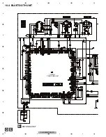
Page 58: ... PST3435UL 1 VOUT 2 VDD 3 NC 4 VSS C35 2 2 2012 Q750 UMF23N 3 2 1 6 5 4 R13 100K R14 100K R12 100K R17 47K R2 100K R3 100K R11 10K DGND R28 680 R29 680 R4 10K R6 47K R5 47K R7 10K R8 47K R9 0 CN1 NM 1 VCC 2 BUSY 3 CLK 4 TXD 5 CE 6 EPM 7 GND 8 RESET 9 CNVss 10 RXD R85 1K R84 1K R83 1K HOLGND DGND ILMGND OELGND R40 47K R35 47K R36 1K CN8 1 HOLGND 2 HOLGND 3 ILMGND 4 OEL_ B 5 ILM_ B 6 OELGND 7 8 SWVD...

Page 59: ...TC74VHC08FTS1 1 1A 2 1B 3 1Y 4 2A 5 2B 6 2Y 7 GND 8 3Y 9 3A 10 3B 11 4Y 12 4A 13 4B 14 Vcc R53 680 R64 680 R65 680 R50 680 R51 680 C50 0 1 C60 0 1 R60 1 8K R61 1 8K R62 3 3K R63 3 3K DGND DGND D851 HZU8 2B3 R71 100 R70 100 C70 0 1 BZ1 PKM13EPY 4000 Q90 UMF23N 3 2 1 6 5 4 R21 100K R24 100K R17 47K R25 47K R1 100K R23 4 7K R22 4 7K R18 2 2K R27 10K R30 680 C10 47P R28 680 R29 680 C2 0 1 C3 0 01 D440...

Page 60: ...VP 44 SVin_PreL C420 4 7 2012 C421 4 7 2012 C422 4 7 2012 C400 4 7 2012 C401 4 7 2012 C402 4 7 2012 C423 1 C424 1 C403 1 C404 1 C413 0 1 C412 0 1 C425 0 22 C405 0 22 C427 2 2 2012 C407 2 2 2012 AGND R411 1K D430 DA204U R431 100K R430 100K DGND MC430 MIC VR430 10K R433 560 C414 10 16 C432 10 16 C415 10 16 R432 2 2K C431 22 16 R551 4 7K R550 4 7K GND L410 2 2uH Q490 UMD2N 3 2 1 6 5 4 Q671 UMD2N 3 2 ...

Page 61: ...00 C70 0 1 BZ1 PKM13EPY 4000 Q90 UMF23N 3 2 1 6 5 4 R21 100K R24 100K R23 4 7K R22 4 7K R18 2 2K R30 680 C10 47P R705 1 4W 3 3K R703 390 PCL OELGND R19 1K D701 RB551V 30 80 L630 2 2uH NJM2885DL1 33 1 IN 2 GND 3 OUT L90 10uH D620 1SS133 C651 0 01 C680 0 01 C701 0 01 JA600 1 FR 2 FR 3 FL 4 ACC 5 FL 6 B REM 7 RL 8 A ANT 9 RL 10 TEL_MUTE 11 RR 12 ILL 13 RR 14 15 GND 16 BU C674 10 16 FR FR FL FL RR RR ...

Page 62: ...3 FMANT 4 VCC 5 SL 6 CE2 7 NC1 8 CE1 9 CK 10 DI 11 LDET 12 OSCGND 13 ROMVDD 14 DO 15 DGND 16 NC2 17 VDD 18 RDS_CK 19 RDS_DATA 20 RDS_LOCK 21 RDS_HSLK 22 AUDIOGND 23 LCH 24 RCH R103 22K AGND C132 0 01 C131 0 01 C133 22 16 C130 10 16 R102 680 R101 680 L410 2 2uH L103 2 2uH L102 2 2uH JA100 RFGND DGND C100 0 1 L101 4 7uH R315 47K GND T290 DLW21HN181SQ2L Q251 UMD2N 3 2 1 6 5 4 D151 HZM6 8ZMWA D150 HZM...

Page 63: ...ELGND CD3 3V BTRFGND BTDGND AVR AVL DACCS DACCK DACDT HFAV OTX ORX BOOTE BTRX BTTX BTBST BTRTS BTTEST BTMUTE BTRST B3V B5V A8V HFAGND MICIN TELOUT TEST BTGND BTPW2 BOOTE2 ORST BTOTX BTORX DGND CN200 USBGND 2 USBGND 3 USBDM 4 USBDP 5 GND 6 DGND 7 LOUT 8 AGND 9 ROUT 1 DGND CN810 1 GND 2 BTPW2 3 BOOTE 4 ORST 5 6 OTX 7 ORX C8 15P C7 15P R281 0 C803 100P C804 0 01 C806 0 01 L3 2 2uH C12 100P D281 SM240...

Page 64: ...16 R926 10K R907 680 R909 680 R914 680 R922 680 R927 680 R930 0 R916 240 R919 240 R911 100 R912 100 R917 240 R920 240 R921 240 HOLGND C911 0 1 F D911 NECBB205T C910 0 1 F C909 0 1 F OELGND DGND KYDT INDTEL INDAV DIM HOLGND DPDT RESET DISPOFF TEL5V AV5V DISP5V R902 1K R903 1K R904 1K CN901 1 DIM 2 INDAV 3 ANDTEL 4 KYDT 5 DPDT 6 RESET 7 DGND 8 DISPOFF 9 SWVDD 1011 OELGND 12 ILM_ B 13 OEL_ B 14 ILMGN...

Page 65: ...2 3 4 5 6 7 8 9 10 11 12 13 14 15 16 17 18 19 R962 47K R959 0 R982 10K R983 10K VSS IREF CVDL VKH VAH XI REGS XCS XRES XCMD SCL SIRX SOTX VSSD V901 OLED MXS8252 1 1 2 3 4 5 5 6 7 8 9 10 10 11 12 13 14 15 15 16 17 18 19 20 20 21 22 23 24 24 C919 0 1 F D919 NECBB205T C930 22P R970 100 R971 100 R972 100 C916 0 1 F R956 82K R954 10K R988 4 7K R989 4 7K C931 0 01 C932 0 01 OELGND RDM CLOCK TA TI PHONE ...

Page 66: ...MOTOR M2 CXC4026 LOADING CARRIAGE MOTOR SWITCHES CD CORE UNIT S10 5COMP2 iPod C2 S901 HOME SWITCH ON OFF S903 DSCSNS SWITCH ON OFF S904 12EJ SWITCH ON OFF S905 8EJ SWITCH ON OFF The underlined indicates the switch position ACTUATOR MOTOR DRIVER F T F T F F T T T F T C S S C T F F F T T S S C C S S C C F T F T 1 2 3 4 5 7 8 9 a c d e f ...

Page 67: ...5 6 7 8 5 6 7 8 C D F A B E C b C C CD CORE UNIT S10 5COMP2 iPod C2 A CN200 iPod AUTHENTICATION COPROCESSOR F SIGNAL LINE FOCUS SERVO LINE TRACKING SERVO LINE CARRIAGE SERVO LINE SPINDLE SERVO LINE T C S 6 b g h i j m l k ...

Page 68: ...FH P800BT XJ UC 68 1 2 3 4 1 2 3 4 C D F A B E C a C b C b 2 1 C CD CORE UNIT S10 5COMP2 iPod C2 F SIGNAL LINE FOCUS SERVO LINE TRACKING SERVO LINE CARRIAGE SERVO LINE SPINDLE SERVO LINE T C S b m ...

Page 69: ...FH P800BT XJ UC 69 5 6 7 8 5 6 7 8 C D F A B E C a C b C b A CN200 iPod AUTHENTICATION COPROCESSOR 6 g h i j m l k ...

Page 70: ... C D F A B E C b C a C a C b 2 1 PICKUP UNIT P10 5 SERVICE SWITCHES CD CORE UNIT S10 5COMP2 iPod C2 S901 HOME SWITCH ON OFF S903 DSCSNS SWITCH ON OFF S904 12EJ SWITCH ON OFF S905 8EJ SWITCH ON OFF F T F T F F T T T F T C S F T F T c d f ...

Page 71: ...M2 CXC4026 LOADING CARRIAGE MOTOR SWITCHES CD CORE UNIT S10 5COMP2 iPod C2 S901 HOME SWITCH ON OFF S903 DSCSNS SWITCH ON OFF S904 12EJ SWITCH ON OFF S905 8EJ SWITCH ON OFF The underlined indicates the switch position ACTUATOR MOTOR DRIVER S C T F F F T T S S C C S S C C 1 2 3 4 5 7 8 9 a e ...

Page 72: ...FH P800BT XJ UC 72 1 2 3 4 1 2 3 4 C D F A B E 10 4 BLUETOOTH UNIT D E COMPOUND UNIT CWX3619 E ANTENNA UNIT ...

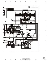
Page 73: ...FH P800BT XJ UC 73 5 6 7 8 5 6 7 8 C D F A B E D D BLUETOOTH UNIT CN800 A ...

Page 74: ...MDX 7SIN 500 mV div 500 mV div 500 mV div 500 mV div 20 ms div FE 0FIN TE 9TIN 1 V div 500 mV div 500 mV div 500 μs div RFAGC TE 9TIN 500 mV div 500 mV div 2 ms div TE RFAGC 500 mV div 500 mV div 200 ms div 0FIN FE Source On setup operation 12 cm CD DA Source On setup operation CD DA Play operation Spindle waveform during play operation Spindle waveform during play operation Wider Focus Search wav...

Page 75: ... div 1DSCSNS 28SNS 312SNS 4LOEJ 5 V div 5 V div 5 V div 500 ms div 1DSCSNS 5CLCONT 4LOEJ 12 cm CD Eject operation Analog audio waveform 12 cm CD Eject operation 8 cm CD Eject operation Black dot 800 µm during play Search operation Outter to Inner 4 Tracks Jump waveform 10 Tracks Jump waveform 32 Tracks Jump waveform Ref REFO Mode TEST Ref REFO Mode TEST Ref REFO Mode TEST Ref GND Mode Normal Ref R...

Page 76: ...FH P800BT XJ UC 76 1 2 3 4 1 2 3 4 C D F A B E 2 V div 2 V div 2 V div 500 ms div CPRST SDA SCL 2 V div 2 V div 50 ms div DP DM ACC OFF with USB iPod device connecting iPod Authentication Operation ...

Page 77: ...FH P800BT XJ UC 77 5 6 7 8 5 6 7 8 C D F A B E ...

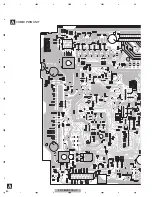
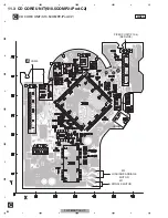
Page 78: ...itor Connector P C Board Chip Part SIDE B SIDE A NOTE FOR PCB DIAGRAMS 1 The parts mounted on this PCB include all necessary parts for several destination For further information for respective destinations be sure to check with the schematic dia gram 2 Viewpoint of PCB diagrams FRONT C CN701 D CN76 CORD ASSY USB AUX ...

Page 79: ...FH P800BT XJ UC 79 5 6 7 8 5 6 7 8 C D F A B E A SIDE A FRONT B CN901 RCA OUT IP BUS ANTENNA FM AM TUNER UNIT ...

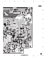
Page 80: ...FH P800BT XJ UC 80 1 2 3 4 1 2 3 4 C D F A B E A A COMBI PWB UNIT ...

Page 81: ...FH P800BT XJ UC 81 5 6 7 8 5 6 7 8 C D F A B E A SIDE B ...

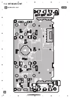
Page 82: ...FH P800BT XJ UC 82 1 2 3 4 1 2 3 4 C D F A B E 11 2 KEYBOARD UNIT B SIDE A B KEYBOARD UNIT MULTI CONTROL ...

Page 83: ...FH P800BT XJ UC 83 5 6 7 8 5 6 7 8 C D F A B E B SIDE B B KEYBOARD UNIT A CN80 ...

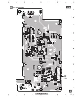
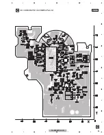
Page 84: ...T XJ UC 84 1 2 3 4 1 2 3 4 C D F A B E 11 3 CD CORE UNIT S10 5COMP2 iPod C2 C SIDE A C CD CORE UNIT S10 5COMP2 iPod C2 HOME M2 LOADING CARRIAGE MOTOR M1 SPINDLE MOTOR REFO1 F E A CN200 PICKUP UNIT P10 5 SERVICE ...

Page 85: ...FH P800BT XJ UC 85 5 6 7 8 5 6 7 8 C D F A B E C SIDE B C CD CORE UNIT S10 5COMP2 iPod C2 8EJ 12EJ DSCSNS ...

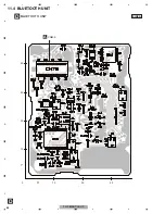
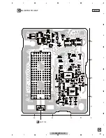
Page 86: ...FH P800BT XJ UC 86 1 2 3 4 1 2 3 4 C D F A B E 11 4 BLUETOOTH UNIT D D BLUETOOTH UNIT SIDE A A CN800 10 20 30 X 40 30 20 10 0 Y ...

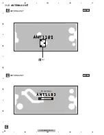
Page 87: ...FH P800BT XJ UC 87 5 6 7 8 5 6 7 8 C D F A B E D D BLUETOOTH UNIT SIDE B 30 20 10 X 40 30 20 10 0 Y E ANT1102 ...

Page 88: ...FH P800BT XJ UC 88 1 2 3 4 1 2 3 4 C D F A B E 11 5 ANTENNA UNIT E E ANTENNA UNIT SIDE A E ANTENNA UNIT SIDE B D CN1 BT ANTENNA ...

Page 89: ...nit Number CZW5575 ES Unit Name Keyboard Unit Unit Number CWN3394 UC EW5 Unit Name Bluetooth Unit Unit Number CWX3624 Unit Name CD Core Unit S10 5COMP2 iPod C2 A Unit Number CZW5569 FH P800BT XJ UC Unit Number CZW5570 FH P8000BT XJ UC Unit Number CZW5568 FH P80BT XJ EW5 Unit Name Combi PWB Unit MISCELLANEOUS IC 1 IC UC PEG437A IC 1 IC EW5 PEG436A IC 35 IC PST3435UL IC 50 IC TC74VHCT08AFTS1 IC 60 I...

Page 90: ... B3 L 1 Inductor CTF1379 L 2 Inductor CTF1379 L 3 Chip Coil CTZ2931 L 90 Chip Coil LCTAW100J2520 L 101 Coil CZT2937 Circuit Symbol and No Part No L 102 Chip Coil CTZ2931 L 103 Chip Coil CTZ2931 L 104 Chip Coil LCTAW4R7J2520 L 105 Inductor LCTAW2R2J2520 L 200 Inductor CTF1379 L 280 Inductor CTH1385 L 410 Chip Coil CTZ2931 L 600 Coil CZT2936 L 630 Inductor LAU2R2J L 700 Inductor CTF1660 L 701 Chip C...

Page 91: ...S1 16S220J R 301 RS1 16S103J R 302 RS1 16S103J R 303 RS1 16S102J R 305 RS1 16S332J Circuit Symbol and No Part No R 306 RS1 16S272J R 307 RS1 16S223J R 308 RS1 16S153J R 309 RS1 16S333J R 310 RK1 16S823J R 311 RS1 16S104J R 312 RS1 16S151J R 313 RS1 16S473J R 315 RS1 16S473J R 316 RS1 16S473J R 317 RS1 16S473J R 318 RS1 16S473J R 319 RS1 16S223J R 320 RS1 16S102J R 321 RS1 16S473J R 322 RS1 16S102J...

Page 92: ...J R 763 RS1 16S332J R 764 RS1 16S562J R 800 RS1 16S102J R 801 RS1 16S102J R 812 RS1 16S102J Circuit Symbol and No Part No R 813 RS1 16S102J R 814 RS1 16S102J R 850 RS1 16S101J R 851 RS1 16S331J R 852 RS1 16S103J R 853 RS1 16S103J R 854 RS1 16S472J R 855 RS1 16S104J R 856 RS1 16S473J R 857 RS1 16S473J R 858 RS1 16S102J R 859 RS1 16S102J CAPACITORS C 1 10 uF 16 V CZC2660 C 2 CKSRYB104K50 C 3 CKSRYB1...

Page 93: ...ZC2971 C 427 CKSQYB225K10 C 431 EW5 CEJQ220M16 C 432 EW5 10 uF 16 V CZC2660 C 433 EW5 CKSRYB474K10 Circuit Symbol and No Part No C 434 EW5 CCSRCH470J50 C 441 CKSRYB103K50 C 442 CKSRYB104K50 C 443 CEAT101M16 C 444 10 uF 16 V CZC2660 C 450 10 uF 16 V CZC2660 C 451 10 uF 16 V CZC2660 C 460 10 uF 16 V CZC2660 C 461 10 uF 16 V CZC2660 C 470 10 uF 16 V CZC2660 C 471 10 uF 16 V CZC2660 C 490 CEJQ220M16 C...

Page 94: ...Q 851 Chip Transistor DTC124EUA Q 852 Transistor 2SD1819A D 35 Diode MA2J11100L Circuit Symbol and No Part No D 80 Diode HZM6R8ZMWA D 81 Diode HZM6R8ZMWA D 82 Diode HZM6R8ZMWA D 83 Diode HZM6R8ZMWA D 100 Diode 1A4 D 101 Diode 1A4 D 160 Diode HZM6R8ZMWA D 161 Diode HZM6R8ZMWA D 250 Diode HZS7L C3 D 280 Diode 1A4 D 281 Diode SM240A D 290 Diode HZM6R8ZMWA D 291 Diode HZM6R8ZMWA D 440 Diode HZS12L B1 ...

Page 95: ...R 357 RS1 16S473J R 362 RS1 16S102J R 364 RS1 16S102J R 370 RS1 16S473J Circuit Symbol and No Part No R 373 RS1 16S473J R 376 RS1 16S473J R 377 RS1 16S473J R 411 RAB4C102J R 430 RS1 16S104J R 431 RS1 16S104J R 440 RS1 16S561J R 441 RS1 16S110J R 450 RS1 16S390J R 451 RS1 16S390J R 452 RS1 16S223J R 453 RS1 16S223J R 460 RS1 16S390J R 461 RS1 16S390J R 462 RS1 16S223J R 463 RS1 16S223J R 481 RS1 16...

Page 96: ...B105K16 Circuit Symbol and No Part No C 282 150 uF 6 3 V CZC2970 C 283 CKSRYB104K50 C 284 CKSRYB103K50 C 286 CCSRCH221J50 C 287 CCSRCH221J50 C 290 CKSRYB104K50 C 291 CKSRYB104K50 C 350 CKSRYB105K10 C 353 CCSRCH220J50 C 354 CCSRCH220J50 C 355 CKSRYB105K10 C 360 CKSRYB103K50 C 361 10 uF 16 V CZC2660 C 362 CEJQ220M16 C 363 CEJQ101M16 C 370 CKSRYB105K10 C 373 CCSRCH220J50 C 374 CCSRCH220J50 C 375 CKSR...

Page 97: ...D 901 LED NECBB205T D 902 LED NECBB205T D 903 LED NECBB205T D 904 LED NECBB205T Circuit Symbol and No Part No D 907 LED NECBB205T D 908 LED NECBB205T D 909 LED UC EW5 NECBB205T D 910 LED UC EW5 NECBB205T D 911 LED NECBB205T D 912 LED NECBB205T D 913 LED NECBB205T D 914 LED NECBB205T D 915 LED NECBB205T D 916 LED NECBB205T D 917 LED NECBB205T D 918 LED NECBB205T D 919 LED NECBB205T D 922 Diode 1SS3...

Page 98: ...F CZC2645 C 921 CKSYF106Z16 C 922 CKSRYB104K50 C 923 CKSRYB104K50 C 924 CKSRYB224K16 Circuit Symbol and No Part No C 925 CKSRYB103K50 C 926 CKSRYB105K10 C 927 CKSRYB104K50 C 930 CCSRCH220J50 C 931 CKSRYB103K50 C 932 CKSRYB103K50 D Unit Number CWN3394 UC EW5 Unit Name Bluetooth Unit MISCELLANEOUS IC 21 IC TC74VHC02FTS1 IC 22 IC TC7PAU04FU IC 23 IC TC7PAU04FU IC 36 IC AK2301A IC 51 IC AN6123MS IC 56...

Page 99: ...K10 C 51 CKSRYB334K10 C 52 CCSRCH331J50 C 53 CKSYB106K6R3 C 54 CKSRYB105K10 C 55 CKSRYB104K16 C 56 CKSYB106K6R3 C 57 CKSRYB102K50 C 58 CKSYB106K6R3 C 59 CKSRYB102K50 C 60 CKSYB106K6R3 C 61 CKSRYB102K50 C 66 CKSYB475K16 C 67 CKSYB475K16 C 68 CCSRCH221J50 C 69 CCSRCH391J50 C 70 CKSYB106K6R3 C 71 CKSRYB105K10 C 72 CCSRCH391J50 C 73 CCSRCH221J50 C 76 CKSRYB102K50 C Unit Number CWX3624 Unit Name CD Cor...

Page 100: ...8 B 15 37 RS1 16S0R0J R 712 B 14 54 RS1 16SS0R0J R 713 B 14 53 RS1 16SS0R0J CAPACITORS C 106 B 56 67 CKSQYB475K6R3 C 202 A 28 57 CKSSYB104K10 C 204 A 23 59 CKSSYB103K16 C 205 B 27 41 CKSQYB475K6R3 C 206 A 23 40 CKSSYB104K10 C 207 A 24 37 CKSRYB104K16 C 209 B 35 34 CEVW220M6R3 C 210 B 29 37 CKSSYB104K10 C 211 A 28 35 CKSSYB104K10 C 212 A 28 30 CKSRYB104K16 Circuit Symbol and No Part No C 213 A 46 3...

Reviews: