background image


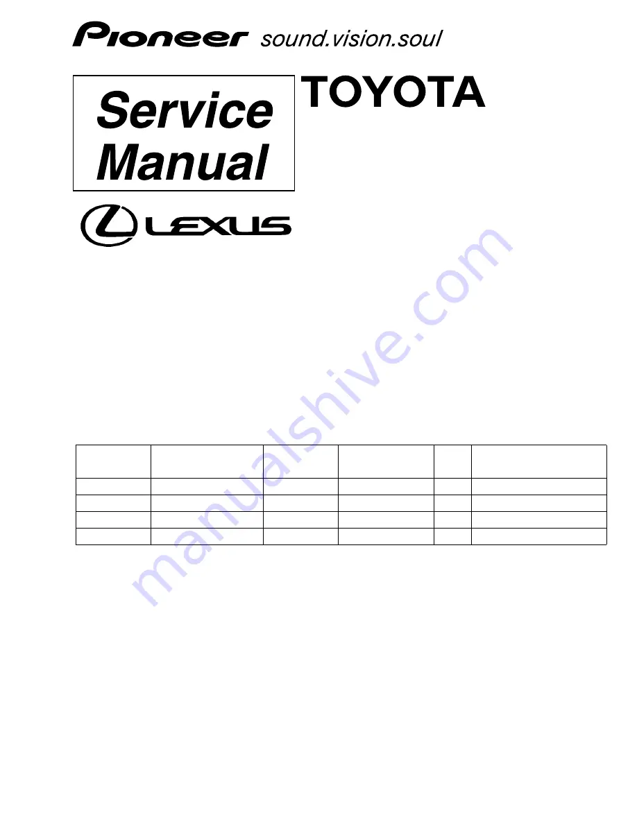
ORDER NO.


CRT3571


RX350

AUDIO SYSTEM

HEAD UNIT


CRT3571


PUB.NO.


Manufactured for TOYOTA

by PIONEER CORPORATION


VEHICLE

DESTINATION

PRODUCED 

AFTER

OEM PARTS No.

ID No.

PIONEER MODEL No.


RX350

EUROPE

January 2006

86120-48A90

P3501

FX-MG8667DVZT/EW

RX350

EUROPE

January 2006

86120-48D10

P3501

FX-MG8667DVZT91/EW

RX350

EUROPE

January 2006

86120-48A60

P3500

FX-MG8767DVZT/EW

RX350

EUROPE

January 2006

86120-48C80

P3500

FX-MG8767DVZT91/EW

Summary of Contents for FX-MG8667DVZT/EW

Page 1: ...CLE DESTINATION PRODUCED AFTER OEM PARTS No ID No PIONEER MODEL No RX350 EUROPE January 2006 86120 48A90 P3501 FX MG8667DVZT EW RX350 EUROPE January 2006 86120 48D10 P3501 FX MG8667DVZT91 EW RX350 EUROPE January 2006 86120 48A60 P3500 FX MG8767DVZT EW RX350 EUROPE January 2006 86120 48C80 P3500 FX MG8767DVZT91 EW ...

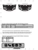
Page 2: ...ssembly DTS and DTS Digital Surround are registered trademarks of Digital Theater Systems Inc Dolby noise reduction manufactured under license from Dolby Laboratories Licensing Corporation Dolby and the double D symbol are trademarks of Dolby Laboratories Licensing Corporation For details refer to Important Check Points for Good Servicing Supplementary model is identical to the original except for...

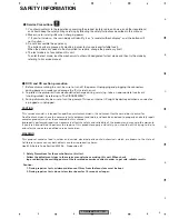
Page 3: ...in electrical parts contain chemicals which are known to the state of California to cause cancer birth defects or other reproductive harm Health Safety Code Section 25249 6 Proposition 65 1 Safety Precautions for those who Service this Unit Follow the adjustment steps in the service manual when servicing this unit When check ing or adjusting the emitting power of the laser diode exercise caution i...

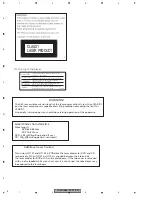
Page 4: ...WARNING The AEL accessible emission level of the laser power output is less than CLASS 1 but the laser component is capable of emitting radiation exceeding the limit for CLASS 1 A specially instructed person should do servicing operation of the apparatus Laser diode characteristics Wave length DVD 640 660nm CD 770 810nm DVD 2 48mW Emitting period 9sec CD 705 W Emitting period unlimited Additional ...

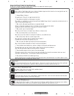
Page 5: ...ide the product Please check that neither solder debris nor screws remain inside the product 8 There should be no semi broken wires scratches melting etc on the coating of the power cord Damaged power cords may lead to fire accidents so please be sure that there are no damages If you find a damaged power cord please exchange it with a suitable one 9 There should be no spark traces or similar marks...

Page 6: ... 11 R PCB 57 3 12 CASSETTE MECHANISM MODULE 58 4 PCB CONNECTION DIAGRAM 62 4 1 MAIN UNIT 62 4 2 KEYBOARD PCB 66 4 3 CONNECTOR1 PCB 70 4 4 CONNECTOR2 PCB 71 4 5 DVD CORE UNIT 72 4 6 PCB ASSY 76 4 7 L PCB 77 4 8 R PCB 78 4 9 DECK UNIT 79 4 10 SENSOR UNIT 80 5 ELECTRICAL PARTS LIST 81 6 ADJUSTMENT 98 6 1 JIG CONNECTION DIAGRAM 98 6 2 DOLBY ADJUSTMENT 99 6 3 TEST MODE 100 7 GENERAL INFORMATION 108 7 1...

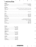
Page 7: ...ithin Dynamic range 80dB or more Cassette player Tape Compact cassette tape C30 C90 Tapespeed 4 76cm sec 0 14cm sec 0 05cm sec Wow and flutter 0 2 or less WRMS Distortion 3 or less S N 40dB or more Crosstalk 40dB or more Stereo Separation 30dB or more FM tuner Frequency 87 5 108 0 MHz S N 46dB or more Distortion 1 5 or less Image interference 35dB or more IF interference 80dB or more AM MW tuner F...

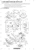
Page 8: ...ist The mark found on some component parts indicates the importance of the safety factor of the part Therefore when replacing be sure to use parts of identical designation Screw adjacent to mark on the product are used for disassembly For the applying amount of lubricants or glue follow the instructions in this manual In the case of no amount instructions apply as you think it appropriate ...

Page 9: ... CN1104 CKS5244 38 Connector CN1003 CKS5251 39 Socket CN1101 CKS5316 40 Holder CND2433 41 Main Unit CWN1110 42 Screw ASZ26P060FTC 43 Screw BMZ30P040FTC 44 Screw M3x6 CBA1393 45 Terminal CN101 CKF1064 46 Terminal CN304 CKF1064 47 Connector CN301 CKM1466 48 Connector CN303 CKM1467 49 Connector CN302 CKM1469 50 Connector CN408 CKS4266 51 Connector CN501 CKS4853 52 Connector CN407 CKS4958 53 Connector...

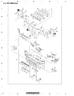
Page 10: ...FX MG8667DVZT EW 10 1 2 3 4 1 2 3 4 C D F A B E 2 2 EXTERIOR 2 ...

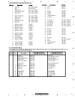
Page 11: ...r CND2773 25 Sheet CNM9563 26 Rubber CNV8536 27 Rubber CNV8537 28 Rubber CNV8538 29 Lighting Conductor CNV8539 30 Connector CNV8540 31 Grille Assy See Contrast table 2 32 Button DISC See Contrast table 2 33 Button TAPE See Contrast table 2 34 Button FM See Contrast table 2 35 Button AM See Contrast table 2 36 Button 1 CAC9217 37 Button 2 CAC9218 38 Button 3 CAC9219 39 Button 4 CAC9220 40 Button 5 ...

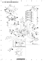
Page 12: ...FX MG8667DVZT EW 12 1 2 3 4 1 2 3 4 C D F A B E 2 3 DVD MECHANISM MODULE G F E ...

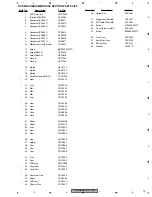
Page 13: ...Gear CND1924 21 Arm CND1926 22 Stair CND1930 23 Stair CND1931 24 Stair CND1932 25 Arm CND1933 26 Gear CND1936 27 Gear CND1937 28 Gear CND1939 29 Case CND2656 30 Plate CND2902 31 Sheet CNM9746 32 Sheet CNM9774 33 Arm CNV7850 34 Gear CNV7851 35 Gear CNV7854 36 Gear CNV7856 37 Holder CNV7861 38 Cam CNV7866 39 Cam CNV7867 40 Cam CNV7868 41 Arm CNV7869 42 Cam CNV7932 43 PCB Assy CWX2986 44 Lever Unit C...

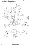
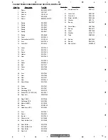
Page 14: ...FX MG8667DVZT EW 14 1 2 3 4 1 2 3 4 C D F A B E 2 4 CASSETTE MECHANISM MODULE For grease application refer to the service manual for CX 1011 CRT2406 I J ...

Page 15: ...569 28 Gear ENV1547 29 Gear ENR1044 30 Worm Wheel ENV1559 31 Lever ENV1551 32 Flywheel ENV1607 33 Gathering PCB ENX1073 34 Switch S101 S102 S103 ESG1007 35 Deck Unit EWM1055 36 Plug CN251 EKS1026 37 Gathering PCB ENX1080 38 Motor Unit M1 EXA1618 39 Motor EXM1035 40 Head Assy HD1 EXA1594 41 Arm ENC1537 42 Screw EBA1031 43 Bracket ENC1559 44 Chassis Unit EXA1636 45 Pinch Holder Unit EXA1608 46 Pinch...

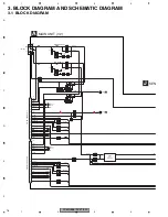
Page 16: ... 16 18 19 20 21 COMP RDSCK RDSDATA RDSLOCK RDSHSLK DO CE1 CK 10 DI 5 SL 6 CE2 7 WC PDI PCE1 PCK PDO PCE2 WC 9 8 3 4 17 13 22 FMANT Y102 14 AUD8 4 VDD3 3 AC5 VCC VDD3 3 DIVER ROMVDD 16 COMP DO CE1 CK 10 DI 5 SL 6 CE2 SPDI SPCE1 SPCK SPDO SSL SPCE2 D105 Q114 Q115 Q105 Q119 2 1 AMP 7 5 IC102 NJM2068V Q116 Q117 SCOMP MCOMP SCPON COMPP COMP MCPON AMPW 2 2 A TUL 11 LDET LDET RCK RDSDT RDSLK RHSLK A Q124...

Page 17: ...NC2N ENC1P ENC1N ENC2P ENC2N ENC1P ENC1M ENC2P ENC2M LCDDO LCDCK LCDCE LCDDI LDTI LCK LCE LDTO PWMBL PINFO LDTI LCK LCE LDTO PWMBL PINFO LDTI LCK LCE LDTO PWMBL PINFO PWMBL P INFO CN408 31 PWMILL PWMILL PWMILL PWMILL PDI PCE1 PCK PDO PCE2 WC PDI PCE1 PCK PDO PCE2 4 3 1 2 5 6 9 10 12 13 14 15 16 17 18 19 20 11 8 7 CN303 B CN802 MAINFIX 6 83 WC SHVSEN RDSLK SHBSEN RDSDT SHVCONT RHSLK C 2 2 A C STBY ...

Page 18: ... VAL TX TXP TXN TXP TXN ADPG NTSC NTS1 NTS2 VV 15 VDD3 3 SWVDD33 19 16 15 AMUTE VDCONT XRESET VDCONT RESET VIDEO SELECTOR IC801 NJM2235V BUS DRIVER IC301 HA12240FP VIN1 VOUT SW1 VSEL STBN DIN1 DOUT AUXIN RX2 RESET RX1 TX IPPW VMUT1 VSEL1 VSEL2 VSEL VMUTE1 VSEL1 VSEL2 SW2 VIN2 VIDEO FILTER VIDEO FILTER IC802 SM5304AV VF VOUT VIN VIDEO SELECTOR IC803 NJM2235V VIN1 VOUT SW1 SW2 VIN2 VIN3 IC804 SM5304...

Page 19: ... SELDATA 22 RLP ALI RNL LP LN 2 1 1 IC209 OPA2134UA Q383 Q386 2 IC210 NJM2068V 2 IC208 OPA2134UA 7 1 3 9 6 7 AMP AUDIO SELECT 6 IC203 NJM4580V IC207 BD3842FS 7 AMP 5 IC205 NJM2068V 5 AMP 7 5 IC201 NJM2068V REMT BMUT INA1 INB1 INE1 INC1 DA CL TUL CDL AUXL L1 L1 LANL OUT1 RECA1 AC5V Q381 Q382 FRMT 9 TX 10 TX TXP TXN AUD B BU Q602 VDCONT Q614 Q609 VD8 VDD5V VD5_ACC VDD3 3 VDD33 SWVDD Q616 1 2 IC601 L...

Page 20: ... 8 1 2 7 6 6 8 9 9 10 10 12 12 ACC B ACC B LCD RST ENCVOL ENCVOL IC VDD IC VDD ENCAUD ENCAUD KEY DO KEY CLK KEY CE KEI DI LDI LCK LCE LDO LDI LCK LCE LDO PWM IND PANEL INFO PWM ILL IC801 LC75804W KEY CONTROL CN802 CN801 CN803 CN980 KEY MATRIX KEY MATRIX ILLMINATION ILLMINATION ILLMINATION Q819 Q820 Q823 Q824 Q826 Q815 ACC 13V DO CE CLOK DI RSET KD1 KD2 KD2 KST1 KD3 KD4 KD3 KD4 78 79 80 KST2 81 82 ...

Page 21: ... IFT LPF TANK RF RF TANK ATT ATT LPF VCO IC1 MIX IF PLL Y102 A Y102 A Y102 A Y102 A FM ANT RFGND OSCGND DGND VCC VDD_3 3 CE2 ROM_VDD SL DI CK CE1 DO 13 5 10 8 14 1 3 2 12 15 4 17 AM ANT 16 23 COMP Lch 24 Rch 22 ANT1 6 9 IC4 5V 3 3V IC3 EEPROM IC2 DET NC MPC MPX DIV RDS REG OSC X tal CF IFT LPF TANK RF RF TANK ATT ATT LPF VCO IC1 MIX IF PLL A FM AM TUNER UNIT FM AM TUNER UNIT RDS_CK RDS_DATA RDS_LO...

Page 22: ...RVO MDQ0 31 DQ0 31 MA0 11 BA0 BA1 BA0 BA1 BA0 BA1 DQM0 3 DQM0 3 DQM0 3 A0 11 DATA BUS ADDRESS BUS 232 238 225 223 22 23 18 19 17 20 68 239 242 XRAS XCAS NRAS NCAS CAS RAS XWE XCSM NWE NCSM WE CS MCK MCK CLK MCKI M5 FLA IC1671 1LE 48 25 2LE ADT0 15 A0 16 A16 18 A16 18 ADT0 15 ADT0 15 A0 15 1Q1 8 2Q1 8 1D1 8 2D1 8 ADT0 15 A0 19 TC74LCX16373AFT LATCH IC1602 TC7SH86FUS1 GATE GATE GATE 41 4 25 38 26 47...

Page 23: ...03 1 SRVDD BVC33 VD5PU VD5 VD5 VD5 VD5 VD8 VD8 VD8 SRVDD BVC33 ROMDATA REV ROMCK ROMCS 50 86 52 51 4 3 2 1 VIDEO GND SPD_SW1 AGND SPD_SW2 5 7 WAKE UP MG WAKEUPMG 1 VD8 SO DI SK CS ANALOG ROUT 6 WAKEUPMG WAKEUP CMDCOMN EXTRGO TRCD0 TRCD2 TRCST TRCD3 TRCD1 TRCCLK XRES_M STSCOMN SDATA SCLOCK DBG_DET 2 20 1 16 11 9 13 14 18 19 8 5 4 6 7 CN1903 XAVCHK_ENT DBG_DET MO1 AO1 SO1 FSEL DACCLK FSSW2 FSSW1 FSS...

Page 24: ...3 A 3 3 A 2 3 A 3 3 A 2 3 A 3 3 A 3 3 A 3 3 A 1 3 A 2 3 A 2 3 A 2 3 A 3 3 A 2 2 E SYSTEM CONTROLLER 2 21dBs 1 0Vrms 3 04dBs 1 1Vrms Decimal points for resistor and capacitor fixed values are expressed as 2 2 2R2 0 022 R022 Symbol indicates a resistor No differentiation is made between chip resistors and discrete resistors NOTE Symbol indicates a capacitor No differentiation is made between chip ca...

Page 25: ...3 C314 315 EW 22K 22K 22K 22K 22P 22P 1K 1K 1K 1K 1K 47K 47K MAIN UNIT 1 3 1 3 A 2 3 A 3 3 A 3 3 A 3 3 A 1 3 A 3 3 2 3 A 2 3 A A 2 3 A 2 3 A 1 3 A 3 3 A 2 3 A 3 3 A SELECTOR UNBALANCE TO BALANCE CONVERTER NTROLLER sistor alues 4A MG4 8 04dBs Mini VTR 7 71dBs FM 4 7dBs AM 1 7dBs CAS 1 8dBs ...

Page 26: ...4 1 2 3 4 C D F A B E A a A b A a A b 1 3 A a 1 3 1 22K 22K 22K 22K 22P 22P 1K 1K 1R8K 1R8K R001 R001 CN1901 2 3 A 2 3 A 3 3 A 3 3 A 1 3 A 2 3 A 2 3 A 2 3 A 3 3 A 2 2 E SYSTEM CONTROLLER 3 04dBs 1 1Vrms PEG164A AM 14dBs FM 17dBs ...

Page 27: ...for resistor and capacitor fixed values are expressed as 2 2 2R2 0 022 R022 Symbol indicates a resistor No differentiation is made between chip resistors and discrete resistors NOTE Symbol indicates a capacitor No differentiation is made between chip capacitors and discrete capacitors The mark found on some component parts indicates the importance of the safety factor of the part Therefore when re...

Page 28: ... E A a A b A b 1 3 1 D302 303 C312 313 C314 315 EW P 1K 1K 1K 47K 47K MAIN UNIT 1 3 1 3 A 3 3 A 3 3 A 1 3 A 3 3 2 3 A 2 3 A A 2 3 A 1 3 A 3 3 A SELECTOR UNBALANCE TO BALANCE CONVERTER LER MG4 8 04dBs Mini VTR 7 71dBs FM 4 7dBs AM 1 7dBs CAS 1 8dBs ...

Page 29: ...FX MG8667DVZT EW 29 5 6 7 8 5 6 7 8 C D F A B E A a A b A b 1 3 2 1R8K 3R3K 1K 1K 3 3 A LER ...

Page 30: ...FX MG8667DVZT EW 30 1 2 3 4 1 2 3 4 C D F A B E 3 3 MAIN UNIT 2 3 GUIDE PAGE A a 2 3 2 3 A 2 3 A 1 3 A 1 3 A 1 3 A 1 3 A 1 3 A 1 3 A M1001 CXM1336 VDD5V REGULATOR 3 3V 1 3 A MAIN UNIT 2 3 ...

Page 31: ...FX MG8667DVZT EW 31 5 6 7 8 5 6 7 8 C D F A B E A b 2 3 A 2 3 1 3 A 1 3 A 1 3 A 1 3 A 1 3 A 1 3 A OR 1 3 A ...

Page 32: ...FX MG8667DVZT EW 32 1 2 3 4 1 2 3 4 C D F A B E A a A b A a A b 2 3 A a 2 3 2 3 A 1 3 A 1 3 A 1 3 A VDD5V REGULATOR 3 3V MAIN UNIT 2 3 ...

Page 33: ...FX MG8667DVZT EW 33 5 6 7 8 5 6 7 8 C D F A B E A a A b A a A b 2 3 A a 2 3 1 2 1 3 A 1 3 A 1 3 A M1001 CXM1336 A ...

Page 34: ...FX MG8667DVZT EW 34 1 2 3 4 1 2 3 4 C D F A B E A a A b A b 2 3 1 3 A 1 3 A 1 3 A 1 3 A OR ...

Page 35: ...FX MG8667DVZT EW 35 5 6 7 8 5 6 7 8 C D F A B E A a A b A b 2 3 1 2 1 3 A 1 3 A 1 3 A 1 3 A ...

Page 36: ...FX MG8667DVZT EW 36 1 2 3 4 1 2 3 4 C D F A B E 3 4 MAIN UNIT 3 3 GUIDE PAGE A a 3 3 3 3 A 2200P 2200P UC EW UC EW 1 3 A 1 3 A ANTENNA DISTRIBUTION ...

Page 37: ...FX MG8667DVZT EW 37 5 6 7 8 5 6 7 8 C D F A B E A b 3 3 A 3 3 2200P 2200P CWE1839 CWE1839 UC EW UC EW UC EW MAIN UNIT 3 3 3 3 A 1 3 A 1 3 A 1 3 A 1 3 A 1 3 A 1 3 A FM COMPOSITE ...

Page 38: ...FX MG8667DVZT EW 38 1 2 3 4 1 2 3 4 C D F A B E A a A b A a A b 3 3 A a 3 3 1 2200P 2200P UC EW UC EW 1 3 A 1 3 A ANTENNA DISTRIBUTION ...

Page 39: ...FX MG8667DVZT EW 39 5 6 7 8 5 6 7 8 C D F A B E A a A b A a A b 3 3 A a 3 3 2 3 ANTENNA DISTRIBUTION ...

Page 40: ...FX MG8667DVZT EW 40 1 2 3 4 1 2 3 4 C D F A B E A a A b A b 3 3 1 2200P 2200P CWE1839 CWE1839 UC EW UC EW C EW MAIN UNIT 3 3 3 3 A 1 3 A 1 3 A FM COMPOSITE ...

Page 41: ...FX MG8667DVZT EW 41 5 6 7 8 5 6 7 8 C D F A B E A a A b A b 3 3 2 3 CWE1839 1 3 A 1 3 A 1 3 A 1 3 A ...

Page 42: ...FX MG8667DVZT EW 42 1 2 3 4 1 2 3 4 C D F A B E 3 5 KEYBOARD PCB B FX MG8767DVZT FX MG8667DVZT FX MG8667DVZT G CN980 ...

Page 43: ...FX MG8667DVZT EW 43 5 6 7 8 5 6 7 8 C D F A B E B H CN990 1 3 A KEYBOARD PCB B CN408 KEYBOARD UNIT Consists of KEYBOARD PCB L PCB R PCB LCD DRIVER ...

Page 44: ...FX MG8667DVZT EW 44 1 2 3 4 1 2 3 4 C D F A B E 3 6 CONNECTOR1 PCB C C CONNECTOR1 PCB D CN1104 CN403 CONNECTOR UNIT Consists of CONNECTOR1 PCB CONNECTOR2 PCB 1 3 A ...

Page 45: ...FX MG8667DVZT EW 45 5 6 7 8 5 6 7 8 C D F A B E 3 7 CONNECTOR2 PCB D D CONNECTOR2 PCB C CN1005 CN1551 Dout CONNECTOR UNIT Consists of CONNECTOR1 PCB CONNECTOR2 PCB 1 2 E ...

Page 46: ...FX MG8667DVZT EW 46 1 2 3 4 1 2 3 4 C D F A B E 3 8 DVD CORE UNIT 1 2 GUIDE PAGE E a 1 2 1 2 E D CN1103 8 9 0 7 6 5 ...

Page 47: ... E b 1 2 E 1 2 F 2 2 E 82K 1R2K 1R2K 6R8K 1 2 E M1 2 2 E 2 2 E R11 5R6K VR11 CCP1442 1k B R14 5R6K VR13 CCW1029 10k B R13 5R6K R12 4R7K VR12 CCP1442 1k B VR2 CCW1023 1k M2 F DVD CORE UNIT 1 2 PCB ASSY SERVICE STAGE ASSY SERVICE STAGE ASSY 3 3 4 2 1 ...

Page 48: ...FX MG8667DVZT EW 48 1 2 3 4 1 2 3 4 C D F A B E A a E b E a E b 1 2 E a 1 2 F 1 D CN1103 8 9 0 7 6 5 ...

Page 49: ...FX MG8667DVZT EW 49 5 6 7 8 5 6 7 8 C D F A B E A a E b E a E b 1 2 E a 1 2 F ...

Page 50: ... 4 1 2 3 4 C D F A B E E a E b E b 1 2 F 1 2 2 E 82K 1R2K 1R2K 6R8K 1 2 E M1 R11 5R6K VR11 CCP1442 1k B R14 5R6K VR13 CCW1029 10k B R13 5R6K R12 4R7K VR12 CCP1442 1k B VR2 CCW1023 1k M2 F DVD CORE UNIT 1 2 PCB ASSY TAGE ASSY 4 ...

Page 51: ...FX MG8667DVZT EW 51 5 6 7 8 5 6 7 8 C D F A B E E a E b E b 1 2 82K 1R2K 1R2K 6R8K 2 2 E 2 2 E SERVICE STAGE ASSY SERVICE STAGE ASSY 3 3 4 2 1 ...

Page 52: ...FX MG8667DVZT EW 52 1 2 3 4 1 2 3 4 C D F A B E 3 9 DVD CORE PCB 2 2 2 2 E R2110 3R9K R2111 12K 1 2 E 1 2 E 1 2 E 1 2 E 9 830MHz ...

Page 53: ...FX MG8667DVZT EW 53 5 6 7 8 5 6 7 8 C D F A B E 2 2 E DVD CORE UNIT 2 2 2 2 E CN407 1 3 A ...

Page 54: ... 3 2 0V div 5ms div Traverse501REV 0 5V div 5ms div 2 3 2 0V div 5ms div Traverse5000FWD 0 5V div 5ms div VHALF VHALF VHALF VHALF VHALF VHALF VHALF VHALF VHALF VHALF VHALF VHALF VHALF VHALF VHALF VHALF 2 3 2 0V div 5ms div Traverse5000REV 0 5V div 5ms div 2 TDY Multi 32REV 0 5V div 500µs div 2 TDY Multi 32FWD 0 5V div 500µs div CH1 TDY CH2 CO CO Waveforms Note 1 The encircled number denote measuri...

Page 55: ... 4 FDY Focus jamp L 0 L1 0 5V div 500µs div 4 FDY Focus jamp L1 L 0 0 5V div 500µs div 4 FDY Play TD 0 5V div 20ms div 4 FDY 0 5V div 1ms div Focus close VHALF 5 CH1 ADOUT0 6 CH2 SRCK 7 CH3 LRCK G 2V div 2µs div G G 8 CH1 LO 9 CH2 RO G 1V div 500µs div G 0 CH1 COMPO 200mV div 10µs div White 100 output G ...

Page 56: ...FX MG8667DVZT EW 56 1 2 3 4 1 2 3 4 C D F A B E 3 10 L PCB G CSD1133 FX MG8767DVZT CSD1132 FX MG8667DVZT B CN801 G L PCB KEYBOARD UNIT Consists of KEYBOARD PCB L PCB R PCB POWER VOL ...

Page 57: ...FX MG8667DVZT EW 57 5 6 7 8 5 6 7 8 C D F A B E 3 11 R PCB H CSD1132 FX MG8767DVZT CSD1133 FX MG8667DVZT B CN803 H R PCB KEYBOARD UNIT Consists of KEYBOARD PCB L PCB R PCB FILE TUNE ...

Page 58: ...302 R1 VR302 33K B 8 24dBs 300mV 1dB Fwd R Fwd L Rev R Rev L NFI L RIN L RIP FIN L GND GND FIN R VREF RIN R NFI R M OUT R EQOUT R TAI R BIAS RAI R PBOUT R DET L MUTE MSGV R MAOUT MSI MSDET MSGV F R 120 70 NR MOUT L EQOUT L TAI L NC RAI L PBOUT L NC DET L MSGV S CN252 CN251 DOLBY B NR IC251 VR301 33K B C310 R1 C309 R1 R321 0R0 VCC CCP1280 CCP1280 NC MSOUT NC NC R260 13K R262 270K C401 3900P R401 15...

Page 59: ... CN256 S103 70µs J L101 L102 J I C354 R01 R362 300 C351 R22 M1 MOTOR UNIT MAIN MOTOR EXA1618 M2 MOTOR UNIT SUB MOTOR EXA1660 CN255 CN254 MOTOR DRIVER IC351 BA6923FP TE VCC2 15 16 17 18 19 20 21 22 23 24 25 26 27 28 14 13 12 11 10 9 8 7 6 5 4 3 2 1 OUT1 NC OUT2 NC PGND TE GND TAB PSO3 PSO2 PSO1 SC2 SC1 CM CE NC NC NC MM NC NC NC TAB VCC1 VCC2 PSB PSI1 PSI2 PSI3 C SM2 SM1 MCS C353 R01 C355 R1 C352 4...

Page 60: ...2 3 CSR Rch 3 4 CSL Lch 4 5 TAPEB TAPE B 5 6 MS MS 6 7 DIR F R 7 8 PLAY PLY 8 9 MTL MTL 9 10 CSMUTE MUTE 10 11 NR NR 11 12 LOAD LOAD 12 13 NC NC 13 14 GND PwrGND 14 15 GND PwrGND 15 16 POS POS 16 17 NC NC 17 18 ES ES 18 19 SC2 SC2 19 20 SC1 SC1 20 21 CM CM 21 22 STBY STBY 22 23 CS12V B UP 23 24 CS12V B UP 24 Connector1 PCB CN1005 Connector2 PCB CN1104 Pin No Connector1 PCBConnector2 PCB Pin No 1 G...

Page 61: ...ILL3 1 2 ILL4 ILL4 2 3 GNDP GNDP 3 4 GNDP GNDP 4 5 KD2 KD2 5 6 GNDD GNDD 6 7 ENRP ENRP 7 8 ENRN ENRN 8 9 KST6 KST6 9 10 KD3 KD3 10 11 NC NC 11 12 KD4 KD4 12 Main Unit CN407 DVD Core Unit CN1901 Pin No Main Unit DVD Core Unit Pin No 1 MAKE UP MG MAKEUP MG 1 2 VIDEO OUT VIDEO OUT YSIG 2 3 VIDEO GND VIDEO GND 3 4 ANA LOUT ANALOG LOUT 4 5 AGND AGND 5 6 ANA ROUT ANALOG ROUT 6 7 AGND AGND 7 8 SPD SW2 SP...

Page 62: ...E FOR PCB DIAGRAMS 1 The parts mounted on this PCB include all necessary parts for several destination For further information for respective destinations be sure to check with the schematic dia gram 2 Viewpoint of PCB diagrams 140 130 120 110 100 90 80 70 60 50 40 30 20 10 10 20 30 40 50 60 70 X 0 Y CAR HARN CAR HARNESS CAR HARNESS C CN1003 E CN1901 I CN251 ...

Page 63: ...FX MG8667DVZT EW 63 5 6 7 8 5 6 7 8 C D F A B E A SIDE A 70 80 90 100 110 120 130 140 150 160 170 180 CAR HARNESS FAN MOTOR M1001 ANTENNA FM AM TUNER UNIT FM AM TUNER UNIT FRONT B CN802 ...

Page 64: ...FX MG8667DVZT EW 64 1 2 3 4 1 2 3 4 C D F A B E A A MAIN UNIT 90 100 110 120 130 140 150 160 170 180 ...

Page 65: ...FX MG8667DVZT EW 65 5 6 7 8 5 6 7 8 C D F A B E A SIDE B 140 130 120 110 100 90 80 70 60 50 40 30 20 10 10 20 30 40 50 60 70 80 90 X 0 Y ...

Page 66: ...ZT EW 66 1 2 3 4 1 2 3 4 C D F A B E 4 2 KEYBOARD PCB B X 110 100 90 80 70 60 50 40 30 20 10 0 Y 10 20 30 40 50 60 70 80 90 100 110 SEEK TRACK L TA R EJECT L LOAD R CAS EJECT L TEXT R FM L TAPE R AM L DISC R 3 2 1 ...

Page 67: ...X MG8667DVZT EW 67 5 6 7 8 5 6 7 8 C D F A B E B B KEYBOARD PCB SIDE A 0 110 120 130 140 150 160 170 180 190 200 210 220 AF L SEEK TRACK R LOAD L EJECT R TEXT L CAS EJECT R DISC L AM R TAPE L FM R 6 5 4 ...

Page 68: ...FX MG8667DVZT EW 68 1 2 3 4 1 2 3 4 C D F A B E B 110 120 130 140 150 160 170 180 190 200 210 220 H CN990 ...

Page 69: ...FX MG8667DVZT EW 69 5 6 7 8 5 6 7 8 C D F A B E B B KEYBOARD PCB SIDE B X 110 100 90 80 70 60 50 40 30 20 10 0 Y 10 20 30 40 50 60 70 80 90 100 110 A CN408 G CN980 ...

Page 70: ...ZT EW 70 1 2 3 4 1 2 3 4 C D F A B E 4 3 CONNECTOR1 PCB C CONNECTOR1 PCB C CONNECTOR1 PCB C SIDE A SIDE B A CN403 CAR HARNESS D CN1104 10 20 30 X 80 70 60 50 40 30 20 10 0 Y 10 20 30 X 80 70 60 50 40 30 20 10 0 Y ...

Page 71: ... MG8667DVZT EW 71 5 6 7 8 5 6 7 8 C D F A B E 4 4 CONNECTOR2 PCB 30 20 10 10 20 30 40 X 0 10 20 30 40 X 0 Y 10 20 30 Y C CN1005 E CN1551 CAR HARNESS D D DOUT D CONNECTOR2 PCB CONNECTOR2 PCB SIDE A SIDE B ...

Page 72: ...FX MG8667DVZT EW 72 1 2 3 4 1 2 3 4 C D F A B E 4 5 DVD CORE UNIT E E DVD CORE UNIT X 100 90 80 70 60 50 40 30 20 10 0 Y 10 20 30 40 50 60 SERVICE STAGE ASSY SERVICE STAGE ASSY M1 A CN407 F D CN1103 ...

Page 73: ...FX MG8667DVZT EW 73 5 6 7 8 5 6 7 8 C D F A B E E SIDE A 60 70 80 90 100 110 120 ...

Page 74: ...FX MG8667DVZT EW 74 1 2 3 4 1 2 3 4 C D F A B E E E 6 70 80 90 100 110 120 DVD CORE UNIT ...

Page 75: ...FX MG8667DVZT EW 75 5 6 7 8 5 6 7 8 C D F A B E E X 100 90 80 70 60 50 40 30 20 10 0 Y 10 20 30 40 50 60 0 SIDE B ...

Page 76: ...FX MG8667DVZT EW 76 1 2 3 4 1 2 3 4 C D F A B E 4 6 PCB ASSY F PCB ASSY F 0 10 20 30 10 20 30 X Y E VR2 VR13 M2 M ...

Page 77: ...7 8 C D F A B E 4 7 L PCB G G L PCB G L PCB SIDE A SIDE B 10 20 30 40 50 60 X 90 80 70 60 50 40 30 20 10 0 Y 60 50 40 30 20 10 X 90 80 70 60 50 40 30 20 10 0 Y B CN801 SEEK TRACK L POWER VOL L FILE TUNE R AST L RTY R AST L RTY R AF R ...

Page 78: ...3 4 C D F A B E 4 8 R PCB H H R PCB H R PCB SIDE A SIDE B 10 20 30 40 50 60 X 90 80 70 60 50 40 30 20 10 0 Y 60 50 40 30 20 10 X 90 80 70 60 50 40 30 20 10 0 Y B CN803 PTY L AST R PTY L AST R TA L SEEK TRACK R FILE TUNE L POWER VOL R ...

Page 79: ...5 10 11 20 21 30 31 40 15 25 35 IC251 R283 R282 R281 R284 VR302 VR301 R288 R321 R287 R272 E Q271 R362 R292 C271 1 5 10 15 20 24 CN251 R401 R402 R403 C404 C405 R404 R275 C272 C403 C402 C401 C310 R273 R276 R278 R277 C309 R271 C301 R259 R257 C255 R261 R296 R255 R251 C251 R254 C254 C252 C253 C302 C256 R252 R253 R258 R260 R262 R256 R361 C354 C357 C351 C353 C360 C361 C362 C363 C355 C364 C352 J CN256 A C...

Page 80: ...FX MG8667DVZT EW 80 1 2 3 4 1 2 3 4 C D F A B E 4 10 SENSOR UNIT J J SENSOR UNIT 1 2 3 4 5 6 S101 LOAD S102 MODE S103 70µs CN256 Q101 REEL SENSE L101 L102 I CN253 ...

Page 81: ...B 97 28 IC HA12240FP IC 401 B 23 38 IC TC7SET08FUS1 IC 502 A 96 33 IC PEG164A IC 503 A 118 24 IC TC7SET08FUS1 IC 504 A 119 33 IC TC74VHC08FTS1 IC 601 A 42 75 IC TPS54350PWP IC 603 B 36 77 IC BA00BC0WFP IC 604 A 52 75 IC TPS54350PWP IC 751 B 26 89 IC S 80940CNNB G9A IC 752 B 22 96 IC S 812C56AUA C3K IC 753 B 22 104 IC S 812C39AMC C2T IC 801 B 50 98 IC NJM2235V IC 802 B 40 99 IC SM5304AV IC 803 B 50...

Page 82: ...ransistor UMX1N Q 751 B 25 96 Transistor UMD12N Q 752 B 15 96 Transistor 2SC4081 Q 753 B 15 88 Transistor 2SC4154 11 Q 754 B 15 91 Transistor 2SA1602A Q 755 A 9 92 Transistor 2SB1185 Q 756 B 20 83 Transistor UMF5N Circuit Symbol and No Part No Q 762 A 23 104 Transistor 2SD1767 Q 801 A 52 99 Transistor DTC144EU D 11 B 137 67 Diode 1SV249 D 12 A 142 59 Diode 1SS355 D 13 B 133 58 Diode DAN217U D 14 B...

Page 83: ...uctor CTH1257 L 602 A 43 59 Inductor CTH1257 L 603 A 54 59 Inductor CTH1257 L 605 A 48 11 Inductor CTF1295 L 701 A 114 56 Inductor CTF1473 L 702 A 137 10 Inductor CTF1295 L 801 A 53 89 Inductor CTF1473 X 501 A 96 20 Radiator 10 0MHz CSS1577 FU301 B 53 140 Fuse 8A CEK1263 EF601 B 44 54 EMI Filter CCG1163 EF602 B 54 54 EMI Filter CCG1163 Circuit Symbol and No Part No RESISTORS R 1 A 134 26 RS1 16SS0...

Page 84: ...83 A 126 99 RS1 16SS223J R 184 A 131 100 RS1 16SS682J R 185 A 130 105 RS1 16SS101J R 186 A 133 106 RS1 16SS683J Circuit Symbol and No Part No R 187 A 133 100 RS1 16SS683J R 188 A 134 106 RS1 16SS682J R 189 A 133 97 RS1 16SS223J R 190 A 128 100 RS1 16SS222J R 201 B 44 118 RS1 10S103J R 202 B 40 116 RS1 10S103J R 203 B 47 118 RS1 10S103J R 204 B 49 116 RS1 10S103J R 205 B 40 114 RS1 16SS562J R 206 B...

Page 85: ...R 346 B 61 134 RS1 10S472J R 347 A 82 40 RS1 16SS473J R 348 A 77 27 RS1 16SS103J Circuit Symbol and No Part No R 349 A 80 25 RS1 16SS152J R 350 B 18 143 RS1 10S102J R 351 B 23 141 RS1 10S102J R 352 A 79 27 RS1 16SS152J R 353 B 87 64 RS1 16SS104J R 354 B 88 64 RS1 16SS103J R 356 A 81 41 RS1 16SS102J R 381 A 98 62 RS1 16SS153J R 382 A 101 64 RS1 16SS153J R 383 A 103 60 RS1 16SS471J R 384 A 97 62 RS1...

Page 86: ...16SS102J R 570 A 110 34 RS1 16SS102J R 571 A 112 34 RS1 16SS102J R 572 A 110 33 RS1 16SS102J Circuit Symbol and No Part No R 573 A 112 33 RS1 16SS102J R 575 A 112 31 RS1 16SS471J R 576 B 103 40 RS1 16SS102J R 577 A 110 30 RS1 16SS102J R 578 A 110 29 RS1 16SS102J R 579 A 110 28 RS1 16SS471J R 580 A 110 27 RS1 16SS102J R 581 A 113 27 RS1 16SS101J R 582 A 113 26 RS1 16SS101J R 583 A 108 24 RS1 16SS10...

Page 87: ...9 RS1 16SS220J R 811 B 12 90 RS1 16SS223J R 812 B 14 94 RS1 16SS224J R 814 B 16 97 RS1 16SS225J R 815 B 20 100 RS1 16SS182J Circuit Symbol and No Part No R 816 B 17 84 RS1 16SS223J R 817 B 17 85 RS1 16SS102J R 818 B 45 99 RS1 16SS3301D R 819 B 46 101 RS1 16SS1001D R 820 B 55 89 RS1 16SS104J R 821 B 55 93 RS1 16SS104J R 822 B 55 95 RS1 16SS105J R 823 B 55 91 RS1 16SS105J R 824 B 45 92 RS1 16SS105J ...

Page 88: ...103 94 CKSSYB102K50 C 215 A 106 97 CCSSCH220J50 C 216 B 102 100 CCSSCH220J50 C 217 B 97 95 CCSSCH220J50 Circuit Symbol and No Part No C 218 B 94 95 CCSSCH220J50 C 219 B 86 97 CKSRYB105K10 C 220 B 87 99 CCSSCH220J50 C 222 B 90 99 CCSSCH220J50 C 223 B 87 94 CCSSCH220J50 C 224 B 84 96 CKSRYB105K10 C 225 B 89 94 CCSSCH220J50 C 226 A 97 87 CKSRYB105K10 C 227 A 95 87 CKSRYB105K10 C 243 A 105 79 CKSSYB10...

Page 89: ...4K50 C 603 A 29 73 470µF 16V CCH1677 C 604 B 61 78 CKSYB225K16 C 605 A 93 140 1000µF 16V CCH1681 P45 Circuit Symbol and No Part No C 606 A 62 86 CKSQYB105K16 C 607 A 66 56 CEVLW470M16 C 608 A 46 80 10µF CCG1182 C 609 A 47 77 10µF CCG1182 C 610 A 45 77 10µF CCG1182 C 611 A 37 77 CKSRYB154K10 C 612 A 38 74 CKSSYB123K16 C 613 A 44 71 CKSSYB104K10 C 614 A 40 71 CKSRYB105K10 C 615 B 44 56 10µF CCG1182 ...

Page 90: ...1104 A 22 4 Inductor LCYB47NJ1608 EF1001 A 63 11 EMI Filter CCG1076 Circuit Symbol and No Part No EF1101 A 7 17 EMI Filter CCG1076 EF1102 A 7 13 EMI Filter CCG1076 EF1103 A 7 21 EMI Filter CCG1076 RESISTORS R 1001 A 65 11 RS1 10S750J R 1101 A 31 10 RS1 10S271J R 1102 A 31 12 RS1 10S101J R 1103 A 23 9 RS1 16SS101J R 1104 A 5 26 RS1 10S750J R 1106 B 36 11 RS1 10S101J R 1107 A 35 10 RS1 10S101J R 110...

Page 91: ...EF1803 B 27 96 EMI Filter DTL1106 EF1901 A 11 20 EMI Filter DTL1106 EF1902 A 13 22 EMI Filter DTL1106 EF1903 B 21 24 EMI Filter DTL1106 EF1905 B 13 15 EMI Filter DTF1106 EF1907 B 21 22 EMI Filter DTL1106 RESISTORS Circuit Symbol and No Part No R 1003 A 85 41 RS1 16SS1003D R 1005 A 83 41 RS1 16SS1501D R 1006 A 85 42 RS1 16SS8202D R 1007 A 83 42 RS1 16SS1502D R 1008 A 81 42 RS1 16SS101J R 1010 A 88 ...

Page 92: ...7 91 RAB4CQ101J R 1574 A 67 88 RAB4CQ101J R 1575 A 67 86 RS1 16SS560J R 1576 A 67 85 RS1 16SS560J Circuit Symbol and No Part No R 1577 A 67 83 RAB4CQ560J R 1578 A 67 81 RAB4CQ560J R 1579 A 69 79 RS1 16SS220J R 1580 A 67 78 RAB4CQ560J R 1581 A 67 76 RS1 16SS560J R 1582 A 67 75 RS1 16SS560J R 1583 A 67 74 RS1 16SS560J R 1584 A 67 72 RAB4CQ560J R 1585 A 67 70 RS1 16SS560J R 1586 A 67 69 RS1 16SS560J ...

Page 93: ... 2022 A 99 49 RS1 16S221J R 2023 A 95 46 RS1 16S221J R 2037 A 98 34 RS1 16SS104J R 2038 A 96 32 RS1 16SS104J R 2040 A 103 29 RS1 16SS104J Circuit Symbol and No Part No R 2041 A 104 27 RS1 16SS221J R 2042 A 104 29 RS1 16SS104J R 2043 A 106 29 RS1 16SS104J R 2044 A 106 27 RS1 16SS104J R 2045 A 107 29 RS1 16SS104J R 2046 A 107 27 RS1 16SS104J R 2047 A 108 29 RS1 16SS104J R 2048 A 108 27 RS1 16SS104J ...

Page 94: ...0 C 1532 A 105 67 CKSSYB103K16 C 1533 A 105 65 CKSSYB103K16 C 1552 A 83 96 CKSSYB104K10 Circuit Symbol and No Part No C 1553 A 90 102 CKSRYB104K25 C 1554 A 87 96 CKSSYB104K10 C 1555 A 87 98 CKSRYB105K10 C 1556 A 100 101 CSZSR470M10 C 1557 A 89 96 CKSSYB104K10 C 1558 A 111 98 CSZS4R7M16 C 1559 A 84 100 CKSRYB105K10 C 1570 B 67 73 CSZSR470M10 C 1571 B 76 77 CKSRYB474K10 C 1572 B 76 85 CKSRYB474K10 C...

Page 95: ...B BGH Unit Number Unit Name Keyboard Unit MISCELLANEOUS IC 801 B 77 74 IC LC75804W Q 801 B 201 81 Transistor 2SA1235A 12 Q 802 B 201 84 Transistor 2SA1235A 12 Q 803 B 20 83 Transistor 2SA1235A 12 Q 804 B 20 79 Transistor 2SA1235A 12 Q 805 B 62 39 Transistor 2SA1235A 12 Q 806 B 157 47 Transistor 2SA1235A 12 Q 808 B 157 50 Transistor 2SA1235A 12 Q 809 B 20 86 Transistor 2SA1235A 12 Q 810 B 201 88 Tr...

Page 96: ... 836 B 49 81 RS1 16S222J R 837 B 53 31 FX MG8767DVZT RS1 16S100J R 838 B 52 28 FX MG8767DVZT RS1 16S100J R 839 B 51 31 FX MG8767DVZT RS1 16S100J Circuit Symbol and No Part No R 840 B 50 28 FX MG8767DVZT RS1 16S100J R 841 B 49 31 FX MG8667DVZT RS1 16S100J R 842 B 48 28 FX MG8667DVZT RS1 16S100J R 843 B 47 31 FX MG8667DVZT RS1 16S100J R 844 B 46 28 FX MG8667DVZT RS1 16S100J R 845 B 190 95 RS1 16S222...

Page 97: ...73 RS1 16S0R0J R 275 RS1 16S473J R 276 RS1 16S104J R 277 RS1 16S224J R 278 RS1 16S104J R 281 RS1 8S0R0J R 282 RS1 8S0R0J R 283 RS1 8S0R0J R 284 RS1 8S0R0J R 287 RS1 8S0R0J Circuit Symbol and No Part No R 288 RS1 8S0R0J R 292 RS1 8S0R0J R 296 RS1 16S0R0J R 321 RS1 8S0R0J R 361 RS1 16S0R0J R 362 RS1 8S301J R 401 RS1 16S153J R 402 RS1 16S332J R 403 RS1 16S911J R 404 RS1 16S274J CAPACITORS C 251 CKSRY...

Page 98: ... Regulated Power Supply H U EMV F TEN 12P 20P 20P 12P 20P 20P 40P 3P 26P 40P 26P 24P 10P 10P 24P 10P 3P GGD1472 24P 8P NAVI AW 24P 8P 3P 3P GGD1451 GVIF GVIF 10P LRHD HANDLE POSITION OPEN L R L LRHD TERMINAL 32P 8P 6P 6P 8P 6P 6P 6P 8P 12P Not used XM Tuner 12P Not used RSE 32P Not used H U 6P AMP MARKLEVINSON Not used VTR 8P Connection Diagram ...

Page 99: ...e discs when the mechanism is placed upside down VR302 mV Meter 2 VR301 L CH R CH Pin2 Pin3 CN251 DECK UNIT Extension Cord GGD1421 DOLBY B NR ADJUSTMENT No Test Tape Adjustment Point Adjustment Method Switch Position 1 NCT 150 VR301 Lch VR302 Rch mV Meter 2 8 24dBm 1dB 400Hz 200nwb m DOLBY NR Switch OFF ...

Page 100: ... U unit operation you can operate MG4 test mode functions but no DVD s normal functions If you want to check DVD s normal function operation be sure to connect EMV N H U with MG4 PC Display AVC LAN Step1 H U with MG4 Periphery Equipment PC power supply serial cable etc Target Device Step 1 Master EMV EMVN System without Step 1 Master H U unit operation 1 2 3 H U with MG4 Periphery Equipment PC pow...

Page 101: ...e times while holding the 1 and 6 buttons see the picture below 2 Touch inside of the framework on the Image Quality Adjustment Screen in the following order Upper Left Lower Left Upper Left Lower Left Upper Left Lower Left see the picture below Press and hold Press three times Upper Left Lower Left Touch the screen in the given order 2 To finish DIAG Mode press and hold the DISC button for 2 seco...

Page 102: ...ation of Go to DIAG Mode see 3 DIAG Mode 2 For operation to finish DIAG Mode see 3 DIAG Mode 4 Operation Specification Normal Mode Go to DIAG Mode DIAG Mode DISC EJECT ILL ON OFF 3 times at H U Test Mode in Preparation Test Mode ACC OFF ACC ON Finish DIAG Mode H U operation Finish DIAG Mode H U operation Standby Mode ACC OFF ...

Page 103: ...ode 2 DISC3 Command for Test Mode 3 Application RPT Command for Test Mode EJECT DISC1 Command for Test Mode 1 Drawing No A Button Command for Test Mode NULL H I TRACK UP TRACK DOWN Command for Test Mode 7 Command for Test Mode 8 G 5 6 F reserve 2 Command for Test Mode 5 Command for Test Mode 6 Command for Test Mode 3 Command for Test Mode 4 D E 3 4 Command for Test Mode 1 Command for Test Mode 2 A...

Page 104: ... test mode Mechanism test mode FE test select EDC1 test select EDC2 test select FE test mode EDC1 test mode EDC2 test mode FE test mode end MG4 test mode 1 4 1 2 3 8 Diagnosis mode Diagnosis mode end Diagnosis mode start Note When you turn off Acc in a static test mode please be sure to check that the mechanism has stopped ...

Page 105: ...ficient Layer1 Tracking Gain Coefficient Layer0 Tracking Gain Coefficient Layer1 AS normalization adjustment feature Layer0 AS normalization adjustment feature Layer1 2FFF 0000 Layer L0 2000 0000 Layer L1 2100 0000 Layer L0 4X00 0000 Layer L1 4X00 0000 3000 0000 3FFF 0000 3B00 0000 DVD x 1 3 1 6CAV CD x 2CLV 4X00 0000 3C00 0000 4A00 0000 Jump 4B00 0000 Jump 4C00 0000 ID display Track number displa...

Page 106: ... Non playable disc NON PLAYABLE DISC 0X90 Different region disc DIFFERENT REGION DISC 0XFF Undefined error Error FF Error code of read error Part of XX Error Code Contents Display 0X99 Data cannot read Please confirm the disc 0X80 The address cannot be found Please confirm the disc 0X90 Focus error Please confirm the disc 0X91 Spindle lock NG DVD is stopping because mechanism detected abnormality ...

Page 107: ...open the claws use the 1 key To close the claws use the 2 key 72 00 Track Minute Second Display 3 To select the LOAD motor press the 5key Default bit11 loadsidesw The states of the loading switches bit12 loadpht bit10 loadoksw Half emp fill OFF ON OFF ON OFF ON E L V L I F T C L M P P L A Y bit2 CamEokSW OFF 01 05 07 06 04 ON OFF ON OFF ON bit1 CamloadSW bit0 CamclampSW The states of the CAM switc...

Page 108: ...on of A and B is order of pushed 6 times in A B A B A and B Service Check screen is displayed 2 Service Check Turn off the ACC B A Check results Check menu Diagnosis clear Memory clear Recheck LAN monitor Device name LAN Mon Code CLR Memory CLR Recheck Old CHEK EXCH OK EMV NAVI CD CH1 CD CH2 MD CH NCON NRES CAMERA MONET System Check Mode Display SCREEN OFF ON BRIGHTNESS CONTRAST Menu Inspection re...

Page 109: ...y operations 1 Diagnosis IN While pressing the CH1 and CH6 With three times of beep sound the mode buttons simultaneously press the change operation completes DISC button three times 2 Diagnosis OUT Keep the DISC button pressed for 1 7 seconds or more and turn the ACC switch OFF 3 Entering the Service check mode Press the TUNE UP button With a beep sound the mode change completes 4 Entering the De...

Page 110: ...are cleared From the details display mode The diagnosis memory data for devices selected is cleared After memory clearance is completed the mode is automatically shifted to the service check mode 6 Key operations for Memory clearance 6 Key operations for Memory clearance Memory clearance automatically ends 3 Key operations for entering Service check mode 4 Key operations for entering the details d...

Page 111: ... Physical address for selected devices The physical address number is displayed whose check result details will follow it Ex P360 Physical address number CD CH Diagnosis data source The detailed items depend on the data source Ex SyS The data was obtained from system check Logical address The logical address number for the device with failure is displayed Ex 1L_63 Logical address number CD CH The ...

Page 112: ...on with controls MONET ECU Vehicle Information ECU 1 DIN Navigation DISPLAY with SW Europe GW ECU Consolidated inside panel Gateway ECU FM multiplex DISPLAY Steering SW Navigation remote controller Fr controlled SW Simple LCD Consolidated SW MD CH commander Body computer 0 8 1 7 9 F 0 8 1 7 9 F 0 1 F 0 8 C 1 7 9 8 D F 0 1 F Navigation computer ATIS VICS TV tuner H W CD CH H W DVD CH TEL informatio...

Page 113: ...ion no response Last mode abnormal Command order no response Mode status abnormal Transmission fault Master reset Slave reset Master abnormal Registration completion acknowledgement error Voice processor ON abnormal ON OFF command or parameter abnormal Registration command transmission Multiple frames intermit Diagnosis no response 00 01 10 11 12 13 20 21 22 23 24 25 26 27 28 29 2A 30 31 D0 D1 D2 ...

Page 114: ...munication error SSDEC communication error SSDEC no response NVM error CAP error No antenna connected Antenna short circuited Disc unreadable DVD abnormal EJECT abnormal Scratches or non recorded side DVD high temperature detected Excessive current detected Tray IN OUT abnormal Elevator abnormal 11 12 13 14 15 16 40 41 42 44 45 46 47 48 50 51 XM C0H DVD CH 45H ...

Page 115: ... the four screws and then remove the Case 1 1 1 Fig 2 Frame Unit Removing the Frame Unit Fig 2 Remove the five screws and then remove the Frame Unit 1 1 Remove the four screws and then remove the Grille Assy 1 1 1 1 1 Removing the Holder Fig 3 Remove the six screws and then remove the Holder 1 Fig 3 Holder 1 1 1 1 1 1 1 There is a claw There is a claw ...

Page 116: ... Holder 1 1 1 Disconnect the connector and then remove the DVD Mechanism Module Fig 6 Holder Removing the Holder Fig 6 1 Remove the four screws and then remove the Holder 1 1 1 1 NOTE Take care not to engage code when wire processing the digital connecting code of DVD mechanism during assembly For service use this specification has a long code for detachable MG4 mechanism part enabling resin parts...

Page 117: ...odule 1 Remove the four screws and then remove the Cassette Mechanism Module 1 1 Fig 9 Removing the Main Unit Fig 9 2 1 Main Unit 1 Straighten the tabs at three locations indicated 1 1 2 2 Remove the two screws and then remove the Main Unit Please refer to Mechanism Manual CRT3495 for removing module part of DVD mechanism Three GGF1538 are necessary to build up MG4 mechanism The Main Unit may appe...

Page 118: ... 19 17 20 10 6 2 3 1 VV 2 VAR 3 VAL 4 VV 5 VA 6 ADPG 1 I02 2 I02 3 MTOR 4 CMP 5 CMP 6 SWG 7 SW1 8 SW2 9 TX 10 TX 11 I01 12 I01 13 SLD1 14 RSLD 15 R R ARI 16 R R ASGN 17 R L ALI 18 R L 19 RMUT AUXI 20 ADIM 1 MUTE 2 CDL 3 CDL 4 CDR 5 CDR 6 CSLD 7 GND 8 NC 9 TXM 10 TXM 11 ACC 12 B 1 B 2 ILL 3 AMP 4 ANTA 5 ATX 6 IVI 7 MUTE 8 R 9 L 10 SLD 11 ACC 12 ILL 13 ANT 14 ANTB 15 ATX 16 IVI 17 SLD2 18 R 19 L 20 ...

Page 119: ...C RECA1 RECA2 RECB1 RECB2 OUT1 OUT2 F SW1 F SW2 JSW1 JSW2 BD3842FS BD3842FS S 80940CNNB G9A PEG164A TPS54350PWP VREF OUT VDD VSS 1 2 4 3 VSS VDD CD OUT CD Delay Circuit S 80940CNNB G9A IC s marked by are MOS type Be careful in handling them because they are very liable to be damaged by electrostatic induction BR93L56RFVM W PE5443A PD6496E TC7SH86FUS1 TC74VHC541FTS1 S 812C39AMC C2T TC7SET08FUS1 MN3...

Page 120: ...ol output 30 LCE O LCD Driver Chip enable output 31 PWMILL O Illumination control output 32 bsrq I P BUS Request input 33 brst O P BUS Reset output 34 RX1 I AVC LAN Data input 35 TX O AVC LAN Data output 36 BSO O P BUS Data output 37 VCC Power supply 38 NC Not used 39 VSS GND 40 41 NC Not used 42 UTX O UART Data output 43 URX I UART Data input 44 PLAY O MS gain select output 45 IRQPW I UART Reques...

Page 121: ...ar monitor mute output 95 isen I Illumination sense input 96 NC Not used 97 asen I ACC power sense input 98 bsen I Back up power sense input 99 101 NC Not used 102 MOTANT I Motor antenna detect input 103 STBY2 O Cassette mechanism driver stand by output 104 MS I Music sense input 105 fR O Cassette mechanism head forward reverse select output 106 CM O Cassette mechanism capstan motor control output...

Page 122: ...ing pin SYNC Bidirectional synchronization I O pin ENA Enable COMP Error amplifier output VSENSE Inverting node error amplifier AGND Analog ground PGND Power ground VBIAS Internal 8 0V bias voltage LSG Gate drive for optional low side MOSFET PH Phase node Connect to external L C filter BOOT Bootstrap capacitor for high side gate driver TPS54350PWP VOUT VSS VIN Reference voltage 1 GND 3 VOUT 2 VIN ...

Page 123: ... SDRAM data IO power supply SDRAM data GND SDRAM data IO power supply Power supply GND Memory address Memory write enable Memory address data IO power supply GND Memory address Memory address data IO power supply GND Memory address data Memory chip select Memory address data Memory address Memory address data IO power supply GND Memory address data Memory output Read enable Memoryaddressbus The fl...

Page 124: ... I I I O O I I O O O I O O I O trigger for debug Output trace clock for debug I O trace data for debug Output trace status for debug Power supply Front end clock input GND Inside monitor Power supply GND Inside monitor Power supply DRC VCO GND DRC VCO Reference voltage gm cEQ gm cEQ Inside analog monitor DPDOFTR Inline data Inline capacitor Reference voltage Analog current Analog GND RF input RF i...

Page 125: ... O O O O O I O O O O O O O O O Analog power suplly Inside DAC bias current Analog GND Inside DAC GND Backend clock input IO power supply Exterior audio clock Composite audio clock LR chanel clock output Bit clock output Audio down mixing GND Audio data IEC958 digital audio output IO power supply GND SDRAM data Power supply SDRAM data IO power supply SDRAM data GND IO power supply SDRAM data GND SD...

Page 126: ... 255 256 VSS NCAS DQM0 VDD15 VSS DQM MDQ VSS MDQ VDD33 MDQ VSS MDQ O O O I O I O I O I O GND SDRAM column address strobe SDRAM data mask Power supply GND SDRAM data mask SDRAM data GND SDRAM data IO power supply SDRAM data GND SDRAM data Pin No Pin Name I O Function and Operation 14 VCC 13 4B 12 4A 11 4Y 10 3B 9 3A 8 3Y 1 1A 2 1B 3 1Y 4 2A 5 2B 6 2Y 7 GND TC74VHC08FTS1 ...

Page 127: ...sm microcomputer reset signal Connected to the oscillator for sub clock connected to VSS via the resistor Connected to the oscillator for sub clock Open Connected to EVDD or EVSS via the resistor Reserve P BUS reset Reserve IIC BUS reset Interruption to the reduced voltage Interruption to rise up the detection of DVD CD DISC insert Reserve P BUS serial data input Reserve P BUS serial data output R...

Page 128: ...ower supply control A pin DVD CD power supply control B pin AV check entry Unit check entry Reserve DVD IN Port SW1 to set the speed of HOST PC UART SW2 to set the speed of HOST PC UART Not used B power supply GND B power supply positive power supply 3 3 V Master clock output control for CD SW1 switching fs CG SW2 switching fs CG PC connected DTR Emphasis ON OFF Switching CD DVD PLL LOCK detection...

Page 129: ...ut Address input Address input Data input output Mode select Chip enable input Output enable input Ready Busy output Reset Acc Power supply GND PD6496E 1 IN B 2 IN A 3 GND 4 OUT Y 5 VCC TC7SH86FUS1 14 Y5 13 Y6 12 Y7 11 Y8 10 GND 9 A8 8 A7 1 g1 2 A1 3 A2 4 A3 5 A4 6 A5 7 A6 15 Y4 16 Y3 17 Y2 18 Y1 19 G2 20 VCC TC74VHC541FTS1 16bit 7bit 16bit CS CS Command decoder Control Clock generation SK SK DI D...

Page 130: ...rite control You can write EEPROM when EEPROM write control is Low Ordinary non connection 8 CE1 I I chip enable 1 Chip enable for AF RF High active 9 CK clock Clock data input 10 DI I data in Data input 11 LDET O lock detector Low active 12 OSCGND osc ground Ground of oscillator block 13 ROM_VDD power supply Power supply for EEPROM pin 13 is connected with a power supply of micro computer 14 DO O...

Page 131: ...FX MG8667DVZT EW 131 5 6 7 8 5 6 7 8 C D F A B E 7 2 2 DISPLAY CAW1867 SEGMENT COMMON ...

Page 132: ...XPLANATION 7 3 1 OPERATIONAL FLOW CHART Power ON Completes power on operation After that proceed to each source operation Source keys operative Source ON bsen L bsen 98 Pin SWVDD L 82 Pin ACCON H 69 Pin asen L asen 97 Pin IPPW H 27 Pin VCC 5V 21 37 85 Pin ...

Page 133: ... B E 7 3 2 SYSTEM BLOCK DIAGRAM B ACC EMV AVC LAN step1 NAVI OTHER MAKERS OTHER MAKERS FM COMP EW model only Small signal interruption audio MAIN SUB Antenna Video AMPLIFIER Audio M U L R AVC LAN step1 PIONEER Steering SPEAKER OTHER MAKERS Switch ...

Page 134: ...OWN UP MANUAL TUNING FM AM SEEK TUNING AST PTY AF TA POWER VOLUME SEEK TUNING TA UP DOWN MANUAL TUNING TRACK NUMBER SEARCH FAST FAST UP DOWN DVD CD LOAD DVD CD EJECT DVD CD TEXT REPEAT DOWN UP RANDOM PLAY DISC NUMBER SEARCH POWER VOLUME FM AM AF PTY AST PRESET CHANNEL MEMORY PRESET CHANNEL RECALL PRESET CHANNEL MEMORY PRESET CHANNEL RECALL ...

Page 135: ...ER SEARCH FAST FAST POWER VOLUME DOWN UP DVD CD EJECT DVD CD LOAD DVD CD REPEAT TEXT DOWN UP DISC NUMBER SEARCH TAPE EJECT TAPE CASSETTE POWER VOLUME REPEAT DOLBY B NR CHANGE SIDES REW FF TAPE EJECT TAPE REPEAT DOLBY B NR CHANGE SIDES REW FF POWER VOLUME AUTO PROGRAM SEARCH REWIND FORWARD AUTO PROGRAM SEARCH REWIND FORWARD ...

Page 136: ...rescribed cleaning tools Portions to be cleaned Cleaning tools DVD CD pickup lenses Cleaning liquid GEM1004 Cleaning paper GED 008 Grease List Name PG641 Jig No GEM1024 Remarks Mechanism Module Unit SERVICE Internal multi DVD shipping position mode setting Auto change to the SHIP MODE after ALL DISC EJECT NOTE Do not switch off ACC and B at the same time immediately after ejecting DISC Switch off ...

Reviews: