background image

FX-MG9727ZT/UC

90

1

2

3

4

1

2

3

4

C

D

F

A

B

E

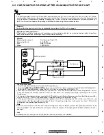
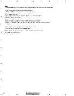
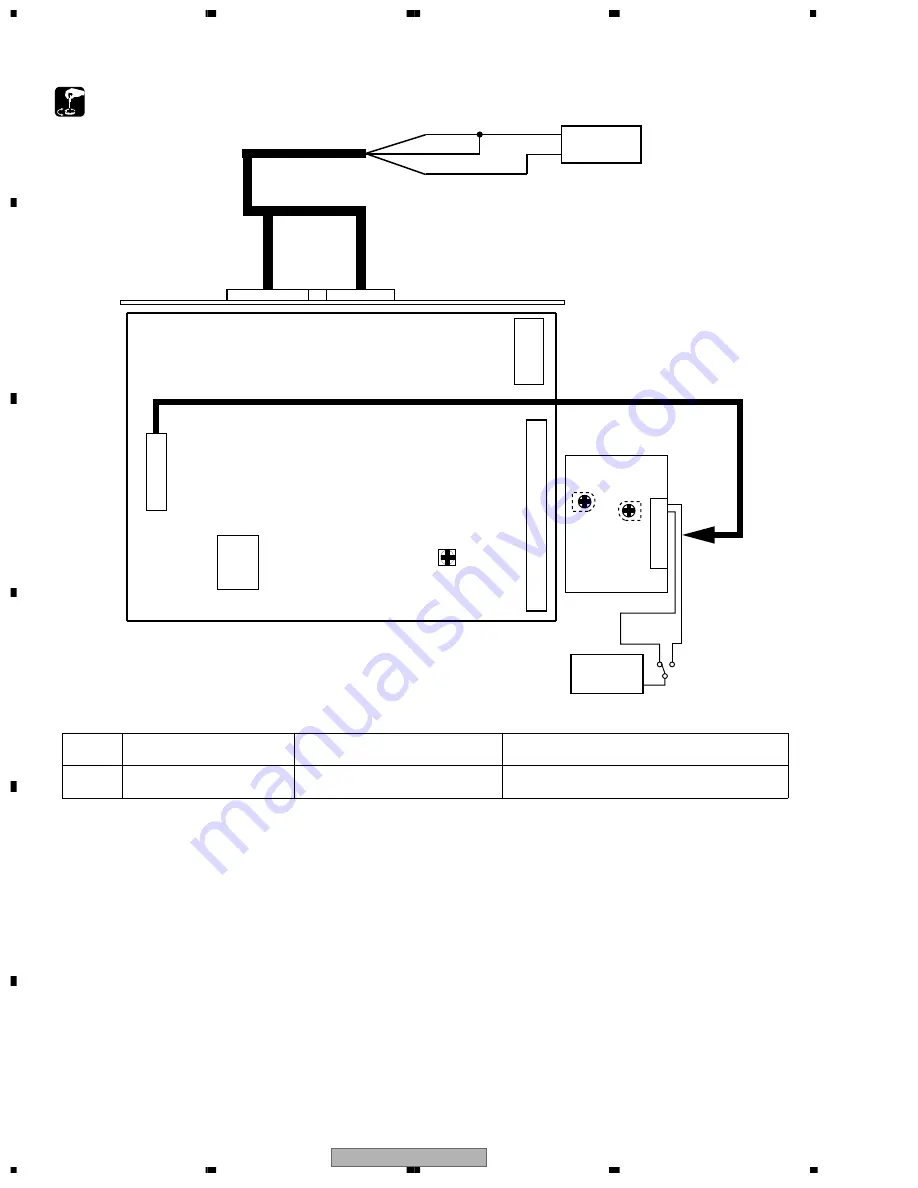
6.2  AUDIO, TUNER ADJUSTMENT

IC601

MAIN UNIT

DC Regulated 
Power Supply

BACK UP

ACC

GND

+13.2V

GND

FM/AM TUNER UNIT

DECK UNIT

Extention Cord  GGD1121

VR561

VR302

mV
Meter(1)

VR301

L-CH

R-CH

Pin2

Pin3

CN251

DECK UNIT

-

Connection Diagram

DOLBY B NR ADJUSTMENT

No.

Test Tape

Adjustment Point

Adjustment Method

(Switch Position)

1

NCT-150

VR301(Lch),VR302(Rch)

mV Meter(1) : –8.24dBm(300mV)

±

1dB

(400Hz,200nwb/m)

(DOLBY NR Switch : OFF)

Summary of Contents for FX-MG9327ZT/EW

Page 1: ...DER NO CRT2905 FX MG9727ZT UC VEHICLE DESTINATION PRODUCED AFTER TOYOTA PARTS NO ID NO PIONEER MODEL No LEXUS LX470 U S A CANADA August 2002 86120 60610 P6823 FX MG9727ZT UC LAND CRUISER EUROPE August 2002 86120 60580 P3916 FX MG9427ZT EW LAND CRUISER EUROPE August 2002 86120 60720 P3917 FX MG9327ZT EW ...

Page 2: ... LOAD PWR VOL PWR VOL AUDIO TUNE AUDIO TUNE 6 DISC CD CHANGER 6 DISC CD CHANGER TYPE TYPE RDS RDS TRAF TRAF SCAN TEXT DISC DISC TAPE TAPE FM FM AM AM SEEK TRACK SEEK TRACK THEFT DETERRENT DESIGN THEFT DETERRENT DESIGN 5 6 5 6 3 4 3 4 1 2 1 2 6 DISC CD CHANGER 6 DISC CD CHANGER LOAD LOAD AUDIO TUNE AUDIO TUNE AST TEXT 5 6 5 6 3 4 3 4 1 2 1 2 PWR VOL PWR VOL THEFT DETERRENT DESIGN THEFT DETERRENT DE...

Page 3: ...ual Improperly performed repairs can adversely affect the safety and reliability of the product and may void the warranty If you are not qualified to perform the repair of this product properly and safely you should not risk trying to do so and refer the repair to a qualified service technician 1 Safety Precautions for those who Service this Unit When checking or adjusting the emitting power of th...

Page 4: ...nces 5 Lubricants glues and replacement parts Appropriately applying grease or glue can maintain the product performances But improper lubrication or applying glue may lead to failures or troubles in the product By following the instructions in this manual be sure to apply the prescribed grease or glue to proper portions by the appropriate amount For replacement parts or tools the prescribed ones ...

Page 5: ... MODULE GUIDE PAGE 40 3 9 CASSETTE MECHANISM MODULE 50 4 PCB CONNECTION DIAGRAM 52 4 1 MAIN UNIT 52 4 2 KEYBOARD UNIT FX MG9727ZT MG9427ZT 56 4 3 KEYBOARD UNIT FX MG9327ZT 58 4 4 CD MECHANISM MODULE 60 4 5 CASSETTE MECHANISM MODULE 66 5 ELECTRICAL PARTS LIST 68 6 ADJUSTMENT 87 6 1 CONNECTION DIAGRAM 87 6 2 AUDIO TUNER ADJUSTMENT 90 6 3 TEST MODE 92 6 4 CD ADJUSTMENT 93 6 5 CHECKING THE GRATING AFT...

Page 6: ...ng frequency 44 1kHz Number of quantization 16 linear S N 65dB or more Distortion 0 3 or less FM tuner Frequency range UC 87 75 87 9 107 9 MHz Frequency range EW 87 5 108 0 MHz S N 46dB or more 54dBµ input Distortion 1 5 or less IF interference 80dB or more Image interference 35dB or more Stereo Separation 25dB or more 1kHz MW AM tuner Frequency range UC 530 1 710 kHz Frequency range EW 522 1 611 ...

Page 7: ...FX MG9727ZT UC 7 5 6 7 8 5 6 7 8 C D F A B E ...

Page 8: ...ES Parts marked by are generally unavailable because they are not in our Master Spare Parts List Screw adjacent to mark on the product are used for disassembly For the applying amount of lobricants or glue follow the instructions in this manual In the case of no amount instructions apply as you think it appropriate ...

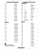
Page 9: ...on CD EJECT CAC7359 43 Button LOAD CAC7360 44 Button 1 2 CAC7361 45 Button 3 4 CAC7362 46 Button 5 6 CAC7363 47 Button See Contrast table 2 48 Button EJECT CAC7365 49 Button See Contrast table 2 50 Button SEEK TRACK CAC7367 51 Button See Contrast table 2 52 Button AM CAC7369 53 Button FM CAC7370 54 Button TAPE CAC7371 55 Button DISC CAC7372 56 Rubber CNV6997 57 Lighting Conductor CNV6999 58 Holder...

Page 10: ...FX MG9727ZT UC 10 1 2 3 4 1 2 3 4 C D F A B E 2 2 EXTERIOR FX MG9327ZT ...

Page 11: ...CNC9701 36 FM AM Tuner Unit CWE1633 37 Holder CNC8855 38 Terminal CN802 VNF1084 39 Terminal CN803 VNF1084 40 Chassis Unit CXB9795 41 Screw BPZ20P080FMC 42 Button LOAD CAC7390 43 Button CD EJECT CAC7391 44 Button 1 2 CAC7361 45 Button 3 4 CAC7362 46 Button 5 6 CAC7363 47 Button AST TEXT CAC7387 48 Button TA CAC7392 49 Button EJECT CAC7393 50 Button AF PTY CAC7394 51 Button SEEK TRACK CAC7395 52 But...

Page 12: ...FX MG9727ZT UC 12 1 2 3 4 1 2 3 4 C D F A B E 2 3 CD MECHANISM UNIT 1 1 1 1 1 3 3 1 1 1 1 1 3 1 2 3 3 3 1 3 3 3 3 3 D F 1 GEM1043 2 GEM1042 3 GEM1024 1 ...

Page 13: ... Lever Unit CXB6936 38 Lever Unit CXB6938 39 Lever Unit CXB6939 40 Cam Motor Assy CXB7522 41 Washer CBF1064 42 Gear CNV6610 43 Gear CNV6611 44 Motor Unit A M1 CXB9726 45 Screw JFZ20P020FMC 46 Washer YE20FUC 47 ELV Motor Assy CXB7523 48 Screw BMZ20P025FMC 49 Washer CBF1064 50 Holder CNC9799 51 Gear CNV6634 52 Gear CNV6635 53 PCB Unit LED CWX2614 54 Connector CN31 CKS4523 55 Motor Unit B M2 CXB7526 ...

Page 14: ...FX MG9727ZT UC 14 1 2 3 4 1 2 3 4 C D F A B E 2 4 CD MECHANISM UNIT 2 2 1 1 1 1 1 1 1 1 1 GEM1043 2 GEM1042 G H E ...

Page 15: ...Unit A CXB7518 22 Carriage Motor Assy CXB7521 23 Washer CBF1038 24 Belt CNT1088 25 Pulley CNV6627 26 Gear CNV6629 27 Motor Unit A M3 CXB7517 28 Screw JFZ14P020FMC 29 Loading Mech Assy CXB7525 30 Washer CBF1037 31 Washer CBF1075 32 Spring CBH2450 33 Spring CBH2452 34 Spring CBH2457 35 Spring CBH2580 36 Frame CNC9228 37 Arm CNC9229 38 Sheet CNM7295 39 Roller CNV6616 40 Collar CNV6617 41 Guide CNV662...

Page 16: ...FX MG9727ZT UC 16 1 2 3 4 1 2 3 4 C D F A B E 2 5 CASSETTE MECHANISM MODULE I J For grease application refer to the service manual for CX 1011 CRT2406 ...

Page 17: ... Gear ENV1547 29 Gear ENR1044 30 Worm Wheel ENV1559 31 Lever ENV1551 32 Flywheel ENV1554 33 Gathering PCB ENX1073 34 Switch S101 S102 S103 ESG1007 35 Deck Unit EWM1043 36 Plug CN251 CKS3540 37 Gathering PCB ENX1076 38 Motor Unit M1 EXA1618 39 Motor EXM1035 40 Head Assy HD1 EXA1594 41 Arm ENC1537 42 Screw JGZ20P025FNI 43 Bracket ENC1559 44 Chassis Unit EXA1636 45 Pinch Holder Unit EXA1608 46 Pinch ...

Page 18: ...FX MG9727ZT UC 18 1 2 3 4 1 2 3 4 C D F A B E ...

Page 19: ...FS MOTOR DRIVER CN1 EC 19 S2 CLAMP HOME S1 HOME 5 2 1 5 2 1 CN42 S41 LOAD3 PCB UNIT 23 14 13 28 26 6 9 10 1 11 12 23 14 13 28 26 6 9 10 1 11 12 PCB UNIT SIDE CN12 S11 CAMCLMP M M1 CAMGEAR CN31 M M2 ELV S32 CAMEOK D31 D32 PCB UNIT LED CN14 CN13 Q22 Q21 S21 LOAD1 S22 LOAD2 PCB UNIT LOAD 2 1 4 5 CN11 MD 23 32 33 LD LD FOP 18 TOP 20 SIN EC 40 CLAMP 36 HOME 37 LOADSW2 45 50 COP 34 COM 35 CGM 3 CGP 1 EL...

Page 20: ...32 33 18 20 40 36 37 45 50 34 35 3 1 15 13 11 10 12 46 48 7 8 6 5 CONTROL UNIT G2T Q101 96 PD CD CONTROL 97 LD A C B D E F L OUT 16 IC504 1 2 TC74VHCT08AFT 3 1 2 IC 201 UPD63711GC 6 5 6 34 LRCKIN 32 SCKIN 3 3V 5V CONVERTER 5V 3 3V CONVERTER IC505 1 2 TC74VHC541FT DOUT LRCK SCKO RADV SBSY 15 ZLRCK 14 ZSCK IC501 SM5903BFP SHOCK PROOF CONTROLLER 10 V 5 22 3V IC507 MSM51V17400F6TFT IC702 PD5748C MECH ...

Page 21: ...MD 6 7 Q864 Q205 sysmute 30 29 21 TX RX1 RX2 isens 22 IPPW 1 2 8 bsens TX RX isens IPPW MUTE RX 56 LANMUTE CN351 Q811 Q813 BU AUDIO B REGULATOR CD 9V REGULATOR BU Q563 1 2 Q564 1 2 Q563 2 2 Q564 2 2 AUDIO B FMB AMB 42 AMPW 41 FMPW TUNL CSL CDL B SWVDD UPD16432B 001 LCD DRIVER IC 902 IC202 TC4052BF IC302 TC4052BF 2 2 3 1 1 4 4 BALANCE TO UNBALANCE CONVERTER IC303 NJM2068MD 6 7 IC304 NJM2068MD 6 7 3...

Page 22: ...IT S103 70µs 4 4 23 32 33 18 20 40 36 37 45 50 34 35 3 1 15 13 11 10 12 46 48 7 8 6 5 CONTROL UNIT G2T Q101 96 PD CD CONTROL 97 LD A C B D E F L OUT 16 IC504 1 2 TC74VHCT08AFT 3 1 2 IC 201 UPD63711GC 6 5 6 34 LRCKIN 32 SCKIN 3 3V 5V CONVERTER 5V 3 3V CONVERTER IC505 1 2 TC74VHC541FT DOUT LRCK SCKO RADV SBSY 15 ZLRCK 14 ZSCK IC501 SM5903BFP SHOCK PROOF CONTROLLER 10 V 5 22 3V IC507 MSM51V17400F6TFT...

Page 23: ... 7 IC204 NJM2068MD 6 7 Q864 Q205 sysmute 30 29 21 TX RX1 RX2 isens 22 IPPW 1 2 8 bsens TX RX isens IPPW MUTE RX 56 LANMUTE CN351 Q811 Q813 BU AUDIO B REGULATOR CD 9V REGULATOR BU Q563 1 2 Q564 1 2 Q563 2 2 Q564 2 2 AUDIO B FMB AMB 42 AMPW 41 FMPW TUNL CSL CDL B SWVDD UPD16432B 001 LCD DRIVER IC 902 IC202 TC4052BF IC302 TC4052BF 2 2 3 1 1 4 4 BALANCE TO UNBALANCE CONVERTER IC303 NJM2068MD 6 7 IC304...

Page 24: ... A b A a A b A b A a Large size SCH diagram Guide page Detailed page Note When ordering service parts be sure to refer to EXPLODED VIEWS AND PARTS LIST or ELECTRICAL PARTS LIST A a A C CN501 I CN251 B CN902 8V 8V 9V FM AM TUNER UNIT AM 30 400Hz 11 7dBs FM 30 400Hz 24 0dBs CD 1kHz 3 8dBs TAPE 1kHz 7 5dBs ...

Page 25: ...f the safety factor of the part Therefore when replacing be sure to use parts of identical designation Symbol indicates a resistor No differentiation is made between chip resistors and discrete resistors NOTE Symbol indicates a capacitor No differentiation is made between chip capacitors and discrete capacitors 9V 8 3V 13 2V 13 2V 5V FM 14 4dBs AM 14 8dBs CD 1 4dBs TAPE 7 5dBs FM 4 6dBs AM 5 0dBs ...

Page 26: ...FX MG9727ZT UC 26 1 2 3 4 1 2 3 4 C D F A B E A a A b A a A a A b 1 2 FM AM TUNER UNIT AM 30 400Hz 11 7dBs FM 30 400Hz 24 0dBs CD 1kHz 3 8dBs ...

Page 27: ...FX MG9727ZT UC 27 5 6 7 8 5 6 7 8 C D F A B E A a A b A a A a A b 3 4 5 6 C CN501 I CN251 B CN902 8V 8V 9V CD 1kHz 3 8dBs TAPE 1kHz 7 5dBs ...

Page 28: ...FX MG9727ZT UC 28 1 2 3 4 1 2 3 4 C D F A B E A a A b A b 1 2 A MAIN UNIT 5V FM 14 4dBs AM 14 8dBs CD 1 4dBs TAPE 7 5dBs ...

Page 29: ...icates the importance of the safety factor of the part Therefore when replacing be sure to use parts of identical designation Symbol indicates a resistor No differentiation is made between chip resistors and discrete resistors NOTE Symbol indicates a capacitor No differentiation is made between chip capacitors and discrete capacitors 9V 8 3V 13 2V 13 2V 5V FM 4 6dBs AM 5 0dBs CD 8 4dBs TAPE 2 3dBs...

Page 30: ... 4 1 2 3 4 C D F A B E 3 5 OVERALL CONNECTION DIAGRAM GUIDE PAGE FX MG9427ZT MG9327ZT A a A 1 2 3 4 5 6 C CN501 I CN251 B CN902 8V 8V 9V FM AM TUNER UNIT AM 30 400Hz 11 7dBs FM 30 400Hz 24 0dBs CD 1kHz 3 8dBs TAPE 1kHz 7 5dBs ...

Page 31: ...tance of the safety factor of the part Therefore when replacing be sure to use parts of identical designation Symbol indicates a resistor No differentiation is made between chip resistors and discrete resistors NOTE Symbol indicates a capacitor No differentiation is made between chip capacitors and discrete capacitors 9V 8 3V 13 2V 13 2V 5V FM 9 5dBs AM 11 5dBs CD 2 7dBs TAPE 7 5dBs FM 3 8dBs AM 5...

Page 32: ...FX MG9727ZT UC 32 1 2 3 4 1 2 3 4 C D F A B E A a A b A a A a A b 1 2 FM AM TUNER UNIT AM 30 400Hz 11 7dBs FM 30 400Hz 24 0dBs CD 1kHz 3 8dBs ...

Page 33: ...FX MG9727ZT UC 33 5 6 7 8 5 6 7 8 C D F A B E A a A b A a A a A b 3 4 5 6 C CN501 I CN251 B CN902 8V 8V 9V CD 1kHz 3 8dBs TAPE 1kHz 7 5dBs ...

Page 34: ...FX MG9727ZT UC 34 1 2 3 4 1 2 3 4 C D F A B E A a A b A b 1 2 A MAIN UNIT 5V FM 9 5dBs AM 11 5dBs CD 2 7dBs TAPE 7 5dBs ...

Page 35: ...icates the importance of the safety factor of the part Therefore when replacing be sure to use parts of identical designation Symbol indicates a resistor No differentiation is made between chip resistors and discrete resistors NOTE Symbol indicates a capacitor No differentiation is made between chip capacitors and discrete capacitors 9V 8 3V 13 2V 13 2V 5V FM 3 8dBs AM 5 8dBs CD 8 4dBs TAPE 1 8dBs...

Page 36: ...FX MG9727ZT UC 36 1 2 3 4 1 2 3 4 C D F A B E 3 6 KEYBOARD UNIT FX MG9727ZT MG9427ZT B ...

Page 37: ...FX MG9727ZT UC 37 5 6 7 8 5 6 7 8 C D F A B E B EARTH SPRING TRAF UC TA EW SEEK TRACK TYPE UC PTY EW RDS UC AF EW SCAN UC AST EW AUDIO TUNE A CN804 B KEYBOARD UNIT ...

Page 38: ...FX MG9727ZT UC 38 1 2 3 4 1 2 3 4 C D F A B E 3 7 KEYBOARD UNIT FX MG9327ZT B ...

Page 39: ...FX MG9727ZT UC 39 5 6 7 8 5 6 7 8 C D F A B E B EARTH SPRING AUDIO TUNE TA AST SEEK TRACK A CN804 B KEYBOARD UNIT ...

Page 40: ...4 CN13 GR BL CN31 RE WH 6 7 8 9 5 4 3 2 1 6 7 8 9 5 4 3 2 1 CN42 CN1 1 2 3 4 5 6 7 8 9 10 11 12 13 14 15 16 17 CN41 1 2 3 4 5 6 7 8 9 10 11 12 13 14 15 16 17 F PCB UNIT SIDE G PCB UNIT H PCB UNIT M2 UNIT D PCB UNIT LED E PCB UNIT LOAD PU UNIT SERVICE PX1 F T C S SIGNAL LINE FOCUS SERVO LINE TRACKING SERVO LINE CARRIAGE SERVO LINE SPINDLE SERVO LINE SL 1 2 3 4 5 6 7 8 9 10 11 12 13 14 15 16 17 18 1...

Page 41: ... UC 41 5 6 7 8 5 6 7 8 C D F A B E C b C SHOCK PROOF MEMORY CONTROLLER BUFFER RAM 3 3V 5V CONVERTER 5V 3 3V CONVERTER MECHANISM CONTROLLER 5V REGULATOR 3 3V REGULATOR MUTE A CN351 C CONTROL UNIT G2T SL SL SL SL 4 ...

Page 42: ...15 16 17 18 19 20 21 22 23 24 25 26 27 28 29 30 CN11 CN12 CN14 6 7 8 9 5 4 3 2 1 6 7 8 9 5 4 3 2 1 CN42 CN1 1 2 3 4 5 6 7 8 9 10 11 12 13 14 15 16 17 CN41 1 2 3 4 5 6 7 8 9 10 11 12 13 14 15 16 17 F PCB UNIT SIDE G PCB UNIT H PCB UNIT M2 UNIT D PU UNIT SERVICE PX1 1 2 3 4 5 6 7 8 9 10 11 12 13 14 15 16 17 18 19 20 21 22 23 24 25 26 27 28 29 30 1 2 3 4 5 6 7 8 1 T T T T T T T T T T SL SL SL SL SL S...

Page 43: ...3 3ch DRIVER 27 28 29 30 1 2 3 4 5 CN14 CN13 GR BL CN31 RE WH 15 16 17 15 16 17 D PCB UNIT LED E PCB UNIT LOAD PU UNIT SERVICE PX1 27 28 29 30 1 2 3 4 5 6 7 8 1 2 3 1 2 3 4 5 6 7 8 F T C S SIGNAL LINE FOCUS SERVO LINE TRACKING SERVO LINE CARRIAGE SERVO LINE SPINDLE SERVO LINE SL The power supply is shown with the marked box C C C C S S S F T F T T T F F F T F T 3 2 4 ...

Page 44: ...FX MG9727ZT UC 44 1 2 3 4 1 2 3 4 C D F A B E C a C b C b 1 SHOCK PROOF MEMORY CONTROLLER BUFFER RAM 3 3V 5V CONVERTER 5V 3 3V CONVERTER 3 3V REGULATOR MUTE A CN351 C CONTROL UNIT G2T SL SL SL SL ...

Page 45: ...FX MG9727ZT UC 45 5 6 7 8 5 6 7 8 C D F A B E C a C b C b 2 3 MECHANISM CONTROLLER 5V REGULATOR 3 3V REGULATOR ...

Page 46: ...3 7 TEC Tracking open Note The encircled numbers denote measuring points in the circuit diagram Mode Test Mode Test CH1 5 RFO CH2 6 TE CH3 8 TDX 1 Track Jump CH1 5 RFO CH2 6 TE CH3 8 TDX 4 Track Jump Mode Test Mode Test CH1 5 RFO CH2 6 TE CH3 8 TDX 10 Track Jump Mode Test CH1 5 RFO CH2 6 TE CH3 8 TDX 32 Track Jump Mode Test ...

Page 47: ...CH4 FG Setup Mode Normal Mode Normal CH1 STSMO CH2 6 TE Memory capacity remaining at the starting of PLAY CH1 9 FE CH2 1 FDX CH3 6 TE CH4 8 TDX During Play Mode Normal Mode Normal CH1 RFO CH2 6 TE Memory capacity remaining during PLAY Mode Normal CH1 LRCK CH2 SCKO CH3 DOUT Digital audio data x2 speed Mode Normal ...

Page 48: ...C 48 1 2 3 4 1 2 3 4 C D F A B E CH1 LOUT CH2 ROUT Audio output 1kHz 0dB CH1 6 TE CH2 8 TDX CH3 SD CH4 4 EC During inside outside search Mode Normal Mode Normal CH1 1 FDX CH2 FOK CH3 MDX CH4 FG DISC stop Mode Normal ...

Page 49: ...FX MG9727ZT UC 49 5 6 7 8 5 6 7 8 C D F A B E ...

Page 50: ...1594 TEST TAPE NCT 150 400Hz 200nWb m RL RR FR FL C302 R1 VR302 33K B 8 24dBs 300mV 1dB Fwd R Fwd L Rev R Rev L NFI L RIN L RIP FIN L GND GND FIN R VREF RIN R NFI R M OUT R EQOUT R TAI R BIAS RAI R PBOUT R DET L MUTE MSGV R MAOUT MSI MSDET MSGV F R 120 70 NR MOUT L EQOUT L TAI L NC RAI L PBOUT L NC DET L MSGV S CN252 CN251 DOLBY B NR IC251 VR301 33K B C310 R1 C309 R1 R321 0R0 VCC CCP1280 CCP1280 N...

Page 51: ... C352 3900P R362 300 C351 R22 C353 R01 C354 R01 R374 0R0 C356 R01 C355 R1 D352 1SS355 M1 MOTOR UNIT MAIN MOTOR EXA1618 M2 MOTOR UNIT SUB MOTOR EXA1623 RS3 RS2 RS1 SC2 SC1 TAB MC CE VCC2 NC VCC MCS RRS FRS RSB C TAB MS2 NC NC MM SM1 RSB GND RS mtl MCS load CN255 CN253 CN254 MECHANISM DRIVER IC351 PA2020A R375 0R0 R404 270K C405 R033 R277 220K R278 100K 71 C4116 SENSOR UNIT S101 LOAD ESG1007x3 S102 ...

Page 52: ...P C Board Chip Part A A MAIN UNIT SIDE B SIDE A NOTE FOR PCB DIAGRAMS 1 The parts mounted on this PCB include all necessary parts for several destination For further information for respective destinations be sure to check with the schematic dia gram 2 Viewpoint of PCB diagrams CAR B CN902 I CN251 C CN501 ...

Page 53: ...FX MG9727ZT UC 53 5 6 7 8 5 6 7 8 C D F A B E A SIDE A FRONT HARNESS CAR HARNESS CAR HARNESS ANTENNA FM AM TUNER UNIT ...

Page 54: ...FX MG9727ZT UC 54 1 2 3 4 1 2 3 4 C D F A B E A A MAIN UNIT ...

Page 55: ...FX MG9727ZT UC 55 5 6 7 8 5 6 7 8 C D F A B E A SIDE B ...

Page 56: ... 3 4 1 2 3 4 C D F A B E 4 2 KEYBOARD UNIT FX MG9727ZT MG9427ZT B B KEYBOARD UNIT SIDE A LOAD AUDIO TUNE TYPE UC PTY EW TEXT DISC TAPE 6 5 4 3 2 1 FM AM CSEJ SEEK TRACK CDEJ PWR VOL RDS UC AF EW TRAF UC TA EW SCAN UC AST EW ...

Page 57: ...FX MG9727ZT UC 57 5 6 7 8 5 6 7 8 C D F A B E B B KEYBOARD UNIT SIDE B A CN804 ...

Page 58: ...FX MG9727ZT UC 58 1 2 3 4 1 2 3 4 C D F A B E 4 3 KEYBOARD UNIT FX MG9327ZT B B KEYBOARD UNIT SIDE A CDEJ PWR VOL SEEK TRACK CSEJ TEXT AM FM AST 6 5 4 3 2 1 TAPE DISC TA LOAD AUDIO TUNE PTY AF ...

Page 59: ...FX MG9727ZT UC 59 5 6 7 8 5 6 7 8 C D F A B E B B KEYBOARD UNIT SIDE B A CN804 ...

Page 60: ...FX MG9727ZT UC 60 1 2 3 4 1 2 3 4 C D F A B E 4 4 CD MECHANISM MODULE C C CONTROL UNIT G2T SIDE A IC Q F CN11 A CN351 REFO E F ...

Page 61: ...FX MG9727ZT UC 61 5 6 7 8 5 6 7 8 C D F A B E C C CONTROL UNIT G2T SIDE B IC Q ...

Page 62: ...FX MG9727ZT UC 62 1 2 3 4 1 2 3 4 C D F A B E D D PCB UNIT LED E PCB UNIT LOAD E F CN14 M M2 ELEVATION RE WH CAMOK CAMLOAD 5 6 7 8 LOAD2 LOAD1 F CN13 ...

Page 63: ...FX MG9727ZT UC 63 5 6 7 8 5 6 7 8 C D F A B E F F PCB UNIT SIDE SIDE A F PCB UNIT SIDE SIDE B 8 D CN31 E C CN101 G M LOADING VR1 ELV SENSE 1 2 3 4 5 GR BL M M1 CAMGEAR ...

Page 64: ...FX MG9727ZT UC 64 1 2 3 4 1 2 3 4 C D F A B E M M3 CRG 1 30 F CN12 1 9 CN42 1 17 CN41 S41 LOAD3 H CN1 PU UNIT SERVICE PX1 L1 G G PCB UNIT ...

Page 65: ...FX MG9727ZT UC 65 5 6 7 8 5 6 7 8 C D F A B E M SPINDLE S1 HOME S2 CLAMP 1 9 CN1 G CN42 C1 R2 R1 IC1 1 5 10 12 13 15 20 24 R4 R3 HE3 HE2 HE1 H H PCB UNIT M2 UNIT ...

Page 66: ...IC351 CN252 CN254 CN253 CN255 M1 M2 HEAD ASSY CN256 21 22 1 10 11 20 21 30 31 40 5 15 25 35 R292 Q271 E R278 R276 R277 R404 C405 C403 C402 C401 C310 C272 R273 R272 R275 R285 R286 R258 C404 R403 R402 R401 C271 IC251 VR302 R283 R282 R281 R284 C253 R253 C252 R252 R287 R296 R321 R288 R255 R261 C255 R257 R259 C301 R271 C309 VR301 C254 R251 C251 R254 C302 R260 C256 R262 R256 R354 R352 R351 R353 E E 1 Q2...

Page 67: ...FX MG9727ZT UC 67 5 6 7 8 5 6 7 8 C D F A B E J 1 2 3 4 5 6 S101 LOAD S102 MODE S103 70µs CN256 Q101 REEL SENSE L101 L102 I CN253 J SENSOR UNIT ...

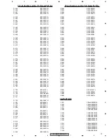
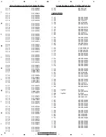
Page 68: ...nsistor 2SC2712 Q 504 Chip Transistor 2SC2712 Q 561 Chip Transistor 2SC2712 Q 563 Transistor IMT2A Q 564 Transistor IMH1A Q 606 Transistor 2SC4081 Q 644 Transistor DTC114EU Q 645 Transistor 2SA1162 Q 721 Transistor DTA114EU Q 722 Chip Transistor 2SC2712 Q 801 Transistor DTC114EU Q 802 Transistor IMX1 Q 805 Transistor DTC144TUA Q 806 Transistor DTC144TUA Q 807 Transistor DTC144TUA Q 808 Transistor ...

Page 69: ...1 Crystal Resonator 3 648MHz CSS1447 X 601 Radiator 10 0MHz CSS1577 VR561 Semi fixed 10kΩ B CCP1396 FU471 Fuse 5A CEK1216 FM AM Tuner Unit CWE1630 EF352 EMI Filter CCG1163 RESISTORS R 1 RS1 16S0R0J R 201 RS1 16S223J R 202 RS1 16S223J R 203 RS1 16S223J Circuit Symbol and No Part NamePart No R 204 RS1 16S223J R 205 RS1 16S223J R 206 RS1 16S223J R 207 RS1 16S223J R 208 RS1 16S223J R 211 RS1 16S101J R...

Page 70: ...RS1 16S225J R 504 RS1 16S225J R 505 RS1 16S222J R 506 RS1 16S104J R 507 RS1 16S103J Circuit Symbol and No Part NamePart No R 508 RS1 16S103J R 509 RS1 16S334J R 510 RS1 16S101J R 511 RS1 16S101J R 512 RS1 16S104J R 513 RS1 16S104J R 514 RS1 16S103J R 515 RS1 16S182J R 516 RS1 16S683J R 517 RS1 16S224J R 518 RS1 16S473J R 519 RS1 16S473J R 520 RS1 16S102J R 522 RS1 16S222J R 525 RS1 16S473J R 526 R...

Page 71: ...2J R 677 RS1 16S102J R 678 RS1 16S102J R 679 RS1 16S102J R 680 RS1 16S102J R 681 RS1 16S102J Circuit Symbol and No Part NamePart No R 682 RS1 16S102J R 683 RS1 16S102J R 684 RS1 16S102J R 685 RS1 16S102J R 687 RS1 16S473J R 689 RS1 16S473J R 690 RS1 16S332J R 691 RS1 16S472J R 692 RS1 16S473J R 698 RS1 16S102J R 699 RS1 16S473J R 701 RS1 16S473J R 703 RS1 4S101J R 704 RS1 4S101J R 705 RS1PMF680J R...

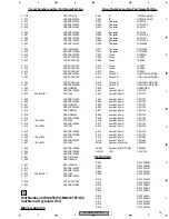
Page 72: ...SRYB104K16 C 253 CEAL220M6R3 C 254 CKSRYB104K16 Circuit Symbol and No Part NamePart No C 256 CCSRCH270J50 C 257 CCSRCH270J50 C 259 CKSRYB104K16 C 260 CCSRCH471J50 C 261 CCSRCH471J50 C 262 CEAL4R7M35 C 263 CKSRYB473K50 C 281 CKSRYB182K50 C 282 CKSRYB182K50 C 283 CKSRYB182K50 C 284 CKSRYB182K50 C 309 CKSRYB102K50 C 310 CKSRYB105K10 C 319 CCSRCH220J50 C 320 CCSRCH220J50 C 321 CCSRCH220J50 C 322 CCSRC...

Page 73: ...2200µF 16V CCH1186 C 805 CKSQYB473K50 C 806 CKSRYB102K50 C 807 CEAL1R0M50 Circuit Symbol and No Part NamePart No C 808 CKSRYB102K50 C 814 CEAL1R0M50 C 815 CEAL1R0M50 C 816 CKSRYB103K50 C 817 100µF 10V CCH1402 C 818 CKSRYB103K50 C 819 100µF 10V CCH1402 C 820 CKSRYB103K50 C 824 CKSRYB472K50 C 825 100µF 10V CCH1402 C 826 CKSRYB472K50 C 827 100µF 10V CCH1402 C 829 CKSRYB103K50 C 830 CKSRYB103K50 C 831...

Page 74: ...G06G 6415G50 D 474 Diode 1SS355 D 475 Diode 1SS355 D 497 Diode UDZS20 B D 501 Diode 1SV241 Circuit Symbol and No Part NamePart No D 502 Diode 1SV241 D 503 Diode DAP202K D 504 Diode 1SS355 D 603 Diode 1SS355 D 703 Diode UDZS18 B D 704 Diode UDZS18 B D 801 Diode 1SS355 D 802 Diode UDZS5R6 B D 803 Diode RM4LFJ10 D 804 Diode 1SS355 D 805 Diode UDZS20 B D 808 Diode HZU8R2 B2 D 809 Diode HZU7R5 B3 D 810...

Page 75: ...16S0R0J R 257 RS1 16S102J R 261 RS1 16S225J R 267 RS1 16S222J R 285 RS1 16S104J Circuit Symbol and No Part NamePart No R 286 RS1 16S104J R 287 RS1 16S104J R 288 RS1 16S104J R 313 RS1 16S163J R 314 RS1 16S163J R 315 RS1 16S163J R 316 RS1 16S163J R 317 RS1 16S163J R 318 RS1 16S163J R 319 RS1 16S163J R 320 RS1 16S163J R 321 RS1 16S103J R 322 RS1 16S103J R 323 RS1 16S103J R 324 RS1 16S103J R 325 RS1 1...

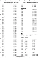
Page 76: ...552 RS1 16S0R0J R 561 RS1 16S104J R 562 RS1 16S123J R 563 RS1 16S105J Circuit Symbol and No Part NamePart No R 564 RS1 16S562J R 567 RS1 16S822J R 568 RS1 16S222J R 569 RS1 16S164J R 570 RS1 16S223J R 571 RS1 16S473J R 582 RS1 16S332J R 583 RS1 16S332J R 584 RS1 16S332J R 585 RS1 16S332J R 601 RS1 16S102J R 602 RS1 16S473J R 603 RS1 16S102J R 604 RS1 16S681J R 605 RS1 16S102J R 606 RS1 16S0R0J R 6...

Page 77: ...819 RS1 16S102J R 820 RS1 16S123J R 821 RS1 16S103J R 822 RS1 16S103J R 823 RS1 16S223J Circuit Symbol and No Part NamePart No R 824 RS1 16S102J R 825 RS1 16S331J R 826 RS1 16S103J R 827 RS1 16S471J R 828 RS1 16S221J R 829 RS1 16S223J R 830 RS1 10S221J R 831 RS1 16S331J R 832 RS1 16S471J R 833 RS1 16S221J R 840 RS1 4S1R5J R 841 RS1 4S1R5J R 842 RS1 4S1R5J R 843 RS1 4S1R5J R 844 RS1 16S471J R 845 R...

Page 78: ...016 C 337 4 7µF 35V CCH1016 C 338 4 7µF 35V CCH1016 C 351 CEAL4R7M35 C 352 CKSRYB103K50 C 353 4 7µF 35V CCH1016 C 354 4 7µF 35V CCH1016 Circuit Symbol and No Part NamePart No C 355 CEAL101M10 C 356 CEAL100M16 C 357 CEAL220M10 C 381 CKSRYB182K50 C 382 CKSRYB182K50 C 383 CKSRYB182K50 C 384 CKSRYB182K50 C 401 CKSRYB123K50 C 402 CKSRYB123K50 C 403 4 7µF 35V CCH1016 C 404 4 7µF 35V CCH1016 C 405 CKSRYB...

Page 79: ...IC 902 IC UPD16432B 001 Q 901 Transistor 2SB1132 Q 902 Transistor DTC123EK Q 903 Transistor 2SB1132 Q 905 Transistor 2SA1162 Q 906 Transistor DTC123EK Q 907 Transistor 2SA1162 Q 908 Transistor DTC123EK Q 909 Transistor DTA144EK Q 911 Transistor DTA144EK Q 912 Transistor DTA144EK D 907 Diode DAP202K D 908 Diode 1SS355 D 909 Diode 1SS355 D 910 Diode 1SS355 D 911 Diode 1SS355 D 912 Diode 1SS355 D 913...

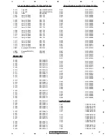
Page 80: ...0R0J R 988 RS1 16S0R0J R 989 RS1 16S0R0J R 990 RS1 16S0R0J Circuit Symbol and No Part NamePart No R 995 RS1 16S0R0J R 996 RS1 16S0R0J R 997 RS1 16S0R0J R 998 RS1 16S0R0J CAPACITORS C 907 CCSRCH101J50 C 908 CCSRCH101J50 C 909 CKSRYB474K10 C 910 CKSRYB103K50 C 911 CKSRYB473K50 C 912 CKSRYB473K50 C 913 CKSRYB473K50 C 914 CKSRYB473K50 C 915 CCSRCH101J50 C 916 CKSRYB103K50 C 917 CKSRYB474K10 C 920 CCSR...

Page 81: ...6S681J R 930 RS1 16S681J R 931 RS1 16S473J R 932 RS1 16S332J R 934 RS1 16S0R0J R 937 RS1 16S103J R 938 RS1 16S473J R 939 RS1 16S473J R 940 RS1 16S473J R 941 RS1 16S473J R 942 RS1 10S151J Circuit Symbol and No Part NamePart No R 943 RS1 10S151J R 944 RS1 10S151J R 945 RS1 10S151J R 946 RS1 16S0R0J R 947 RS1 16S0R0J R 948 RS1 16S0R0J R 949 RS1 16S0R0J R 950 RS1 16S0R0J R 951 RS1 16S0R0J R 952 RS1 16...

Page 82: ...909 Lamp 8V 60mA CEL1722 IL 910 Lamp 8V 60mA CEL1722 IL 911 Lamp 8V 60mA CEL1722 IL 912 Lamp 8V 60mA CEL1722 IL 913 Lamp 8V 60mA CEL1722 IL 914 Lamp 8V 60mA CEL1722 IL 915 Lamp 8V 60mA CEL1684 IL 916 Lamp 8V 60mA CEL1684 Circuit Symbol and No Part NamePart No VR901 Encoder AUDIO TUNE CSD1082 VR902 Encoder PWR VOL CSD1078 LCD901 LCD CAW1702 RESISTORS R 900 RS1 16S0R0J R 901 RS1 16S0R0J R 902 RS1 16...

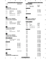
Page 83: ...G2T Circuit Symbol and No Part NamePart No MISCELLANEOUS IC 201 IC UPD63711GC IC 301 IC BD7962FM IC 302 IC S 818A33AUC BGN IC 303 IC BA05SFP IC 501 IC SM5903BFP IC 504 IC TC74VHCT08AFT IC 505 IC TC74VHC541FT IC 507 IC MSM51V17400F6TFT IC 702 IC PD5748C Q 101 Transistor 2SB1132 Q 601 Transistor DTC114EK Q 602 Transistor DTA123JK Q 603 Transistor DTC314TK Q 604 Transistor DTC314TK Q 702 Transistor U...

Page 84: ...S222J R 743 RS1 16S681J R 758 RS1 16S153J R 759 RS1 16S103J R 760 RS1 16S433J Circuit Symbol and No Part NamePart No R 767 RS1 16S154J R 775 RAB4CQ681J CAPACITORS C 101 CKSRYB103K25 C 102 CKSRYB104K25 C 103 CEVL101M10 C 104 CEVL470M6R3 C 105 CKSRYB224K16 C 106 CKSRYB224K16 C 107 CKSRYB224K16 C 201 CKSRYB104K25 C 202 CEVL220M16 C 203 CKSRYB473K25 C 204 CKSRYB182K50 C 205 CKSRYB104K25 C 206 CKSRYB15...

Page 85: ...04K25 H Unit Number Unit Name PCB Unit M2 Unit Circuit Symbol and No Part NamePart No MISCELLANEOUS IC 1 IC BA6849FS S 1 Switch HOME CSN1057 S 2 Switch CLAMP CSN1057 RESISTORS R 1 RS1 16S221J R 2 RS1 16S221J R 3 RS1 16S4R7J R 4 RS1 16S1R0J CAPACITORS C 1 CKSRYB104K16 I Unit Number EWM1043 Unit Name Deck Unit MISCELLANEOUS IC 251 IC HA12216F IC 351 IC PA2020A Q 271 Transistor 2SC4116 D 352 Diode 1S...

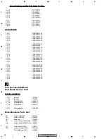
Page 86: ... 353 CKSRYB103K50 C 354 CKSRYB103K50 C 355 CKSQYB104K50 C 356 CKSRYB103K50 C 401 CKSRYB392K50 C 402 CKSRYB334K10 C 403 CKSRYB223K25 C 404 CKSRYB103K50 C 405 CKSRYB333K16 J Unit Number EWM1041 Unit Name Sensor Unit MISCELLANEOUS L 101 Inductor CTF1546 L 102 Inductor CTF1546 S 101 Switch LOAD ESG1007 S 102 Switch MODE ESG1007 S 103 Switch 70µS ESG1007 Q 101 Photo reflector EGN1004 Miscellaneous Part...

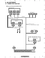
Page 87: ...tor To DC Regulated Power Supply H U 12P 20P 20P 25P 16P 16P 20P 25P GGD1240 FR FR AMP M L GGD1302 Bullet connector To DC Regulated Power Supply 20P 18P 10P 6P 10P 14P 12P 20P 24P 32P MCD MDVD NAVI ECU DENSO EMV DENSO Please don t connect MCD and MVD at the same time MCD or MDVD does not operate if RSAcontroller is not connected Connection Diagram FX MG9727ZT UC ...

Page 88: ...ullet connector To DC Regulated Power Supply H U 12P 20P 20P 25P 16P 16P 20P 25P GGD1240 FR FR AMP GGD1303 Bullet connector To DC Regulated Power Supply 24P 18P 10P 10P 14P 12P 20P 24P 12P MCD MCD NAVI ECU A W Please don t connect MCD L and MCD R at the same time MCD does not operate if RSAcontroller is not connected Connection Diagram FX MG9427ZT EW MG9327ZT EW ...

Page 89: ...A B E Bullet connector To DC Regulated Power Supply Bullet connector SP Line H U 12P 20P 20P 25P 16P 16P GGD1169 20P 25P GGD1240 GM 9227ZT E L GM 9527ZT WL R FX MG9427ZT EW L FX MG9327ZT EW R AMP Connection Diagram FX MG9427ZT EW MG9327ZT EW ...

Page 90: ... GND 13 2V GND FM AM TUNER UNIT DECK UNIT Extention Cord GGD1121 VR561 VR302 mV Meter 1 VR301 L CH R CH Pin2 Pin3 CN251 DECK UNIT Connection Diagram DOLBY B NR ADJUSTMENT No Test Tape Adjustment Point Adjustment Method Switch Position 1 NCT 150 VR301 Lch VR302 Rch mV Meter 1 8 24dBm 300mV 1dB 400Hz 200nwb m DOLBY NR Switch OFF ...

Page 91: ...with 1 condition 3 Mix signal with the above mentioned pulse and SSG moduration OFF 4 Variable resistance adjust noise level to a minimam Adjustment point VR561 Pulse generator equivalent to HP8011A SSG 2 signal pad AM dummy KEX M8406ZT Output Noise meter Pulse width 50usec Pulse intervals 5msec Pulse voltage 4Vp p 4Vp p EMF 50us 5ms AM NOISE CANCELER ADJUSTMENT FX MG9727ZT UC FX MG9427ZT EW FX MG...

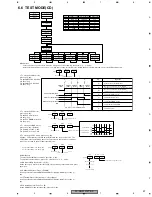
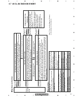
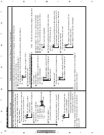
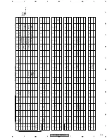
Page 92: ...displayed CD ERRXX 3 DOWN 4 External CD CH Error number displayed CD ERRXX DISC for 1 7 seconds DIAG End Normal display Rest the Microcomputer to return to the normal mode 2 Notes 1 Depending on the state of DIAG 2 Note that the test mode is cancelled in the system microcomputer by switching the ACC OFF and ON but that it is not in the CD microcomputer Use the reset function for complete cancellat...

Page 93: ...ned on various protective functions from the software become unavailable Thus you must make sure that undesirable electric or mechanical shocks are not be given to the system This model employs a photo transistor for detecting discs at their loading or ejection Thus if its outer case is removed during repair work and internal parts are exposed to light of strong intensity malfunctions including th...

Page 94: ...n Focus Close S Curve Rough Servo RF AGC F T RF AGC CRG TR Jump Toward inner perimeter Error occurrence time Cause display switching SEEK UP SEEK DOWN LOAD EJECT DISC load DISC load DISC eject DISC eject MIN SEC TRK MIN SEC TRK 00 00 00 MIN SEC TRK 99 99 99 MIN SEC TRK 00 00 72 MIN SEC TRK 5 RF AMP Gain Select 1 MIN SEC TRK 00 00 00 MIN SEC TRK MIN SEC TRK MIN SEC TRK MIN SEC TRK 91 91 91 MIN SEC ...

Page 95: ... buttons move the PU unit to the innermost track FX MG9727ZT MG9427ZT Using the PTY and AF buttons move the PU unit to the innermost track FX MG9327ZT 3 Press key 5 to close focus the display should read 91 Press key 2 to implement the tracking balance adjust ment the display should now read 81 Press key 5 4 times The display will change returning to 81 on the fourth press 4 As shown in the diagra...

Page 96: ...FX MG9727ZT UC 96 1 2 3 4 1 2 3 4 C D F A B E Grating waveform Ech Xch 20mV div AC Fch Ych 20mV div AC 45 0 75 60 30 90 ...

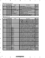
Page 97: ...2 loadpht bit10 loadoksw Half emp fill OFF ON OFF ON OFF ON E L V L I F T C L M P P L A Y bit2 CamEokSW OFF CAM1P 01H CAM1P 01H CAM1P 01H CAM1P 01H CAM1P 01H ON OFF ON OFF ON bit1 CamloadSW bit0 CamclampSW The states of the CAM switches Key 1 Operation To the mech test initial state Selects the CAM motor Selects the ELV motor Selects the LOAD motor Selects the DISC CLAMP Selection reset Moves the ...

Page 98: ...d by forced ejection 3 The LOAD SW value 3 bits at the forced ejection end CAM motor FWD time out error during TRAY UP operation CAM motor REV time out error during TRAY UP operation CAM motor FWD time out error during TRAY DN operation CAM motor REV time out error during TRAY DN operation CAM motor FWD2 time out error during TRAY DN operation CAM motor FWD time out error during CRG OUT operation ...

Page 99: ...n ELV motor REV time out error during LIFT DN operation Over count error during LIFT DN operation DISC IN SIDE SW ON is sensed during door close operation Overrun error during LIFT DN operation Pincheddisc issensedduringLIFTDNoperation withintherangeof 1LSB 200mscontinued Current disc No The ELV error stop position before retry 5 CAMRST Forced ejection Door open close error LOAD SW error during HL...

Page 100: ... FwdTo 1 RevTo 2 Chata 3 OverCnt 4 SwNg 5 SpdNg 6 Fwd2To 7 Rev2To 8 Sw2Ng 9 4 The last results of chatter check compared with the target center 8LSB 1 7LSB 2 6LSB 3 5LSB 4 4LSB 5 3LSB 6 2LSB 7 1 0LSB 8 1 0LSB 8 2LSB 9 3LSB a 4LSB b 5LSB c 6LSB d 7LSB e 8LSB f the others 0 5 Basically the value of eudpzt except for the following case In case of eudpzt 1 and door close mode eudpzt e 6 bit0 P_lo1 bit...

Page 101: ...es connected are cleared From the details display mode The diagnosis memory data for devices selected is cleared After memory clearance is completed the mode is automatically shifted to the service check mode 6 Key operations for Memory clearance 6 Key operations for Memory clearance Memory clearance automatically ends 3 Key operations for entering Service check mode 4 Key operations for entering ...

Page 102: ...Physical address for selected devices The physical address number is displayed whose check result details will follow it Ex P360 Physical address number CD CH Diagnosis data source The detailed items depend on the data source Ex SyS The data was obtained from system check Logical address The logical address number for the device with failure is displayed Ex 1L_63 Logical address number CD CH The l...

Page 103: ...V Europe navigation DISP M U Rear TV with movie mode Navigation with controls MONET ECU Vehicle Information ECU 1 DIN Navigation DISPLAY with SW Europe GW ECU Consolidated inside panel Gateway ECU FM multiplex DISPLAY Steering SW Navigation remote controller Fr controlled SW Simple LCD Consolidated SW MD CH commander Body computer 0 8 1 7 9 F 0 8 1 7 9 F 0 1 F 0 8 C 1 7 9 8 D F 0 1 F Navigation co...

Page 104: ...on abnormal Connecting confirmation no response Last mode abnormal Command order no response Mode status abnormal Transmission fault Master reset Slave reset Master abnormal Registration completion acknowledgement error Voice processor ON abnormal ON OFF command or parameter abnormal Registration command transmission Multiple frames intermit Diagnosis no response 00 01 10 11 12 13 20 21 22 23 24 2...

Page 105: ...g 1 Disconnect the connector and then remove the Grille Assy Removing the Grille Assy Fig 1 Fig 2 Grille Assy Frame 1 Remove the five screws and then remove the Frame 1 1 1 1 1 1 1 1 1 1 1 1 1 1 1 Case and Chassis Unit Removing Case and Chassis Unit Fig 3 1 Remove the eight screws Fig 3 Disconnect the connector and then remove the Case and Chassis Unit ...

Page 106: ...5 Straight the tabs at three locations indicated 2 Remove the two screws and then remove v the Main Unit 2 Main Unit Removing the Cassette Mechanism Module u Fig 4 Fig 4 Cassette Mechanism Module Remove the four screws and then remove v the Cassette Mechanism Module 1 2 1 1 1 1 1 1 1 ...

Page 107: ...hanism Unit Fig 6 1 Remove the two springs A and two springs B 2 Remove the three screws A and then remove the Bracket Unit 3 Remove the four Dampers and then remove the CD Mechanism Unit Removing the Control Unit G2T Fig 6 1 Remove the eight screws and then remove the Case 2 Apply shorting solder to the PU flexible cable before disconnecting it from the connector 3 Disconnect the connector 4 Remo...

Page 108: ... CD mechanism to put it into the initial mode where the carriage mech assy stays at the disc clamp position in accordance with the following method Initial mode setting method 1 Keep a CD mechanism unit out of the product to be serviced as shown below Connect the 50 pin connector of the control unit G2T in the product and the 50 pin connector of the PCB unit Side in the CD mechanism by using the e...

Page 109: ...isconnect the flexible cable from the connector CN12 and remove the flexible cable Holder 6 Remove the washer and Arm Be careful not to lose the spring B 7 Remove the screw spring A and Collar 8 Remove the Carriage Mech Assy Fig 8 9 Apply shorting solder to the PU flexible cable before disconnecting it from the Connector 10 Disconnect the PU flexible cable from the Connector 11 Move the PU Unit to...

Page 110: ...27ZT UC 110 1 2 3 4 1 2 3 4 C D F A B E 7 1 2 PCB LOCATIONS MAIN UNIT KEYBOARD UNIT CONTROL UNIT G2T A B C F E G H D PCB UNIT SIDE PCB UNIT PCB UNIT M2 UNIT PCB UNIT LOAD PCB UNIT LED SENSOR UNIT J DECK UNIT I ...

Page 111: ...E 7 1 3 CONNECTOR FUNCTION DESCRIPTION SHIP SW1 TX1 NC NC NC NC SLD1 RSR GND NC RSL NC SW2 RSL RMUTE RSR ADIM TX1 NC NC L GND SGND R R L MUTE BU ACC TX TX NC ILL ACC B ILL ANT AMP NC NC TX TX NC NC NC MUTE R R L L GND SLD SUB ANTENNA MAIN ANTENNA ...

Page 112: ...ed 27 DRST O RDS Decoder reset output 28 NC Not used 29 RX1 I IP BUS Data input 30 TX O IP BUS Data output 31 PDO O Tuner PLL IC data output 32 PDI I Tuner PLL IC data input 33 pck O Tuner PLL IC clock output 34 PCE1 O Tuner PLL IC chip select output 35 BSO O P BUS Serial data output 36 BSI I P BUS Serial data input 37 BSCK O P BUS Serial clock output 38 brxen I O P BUS Reception enable input outp...

Page 113: ...pe end sense input 77 SC2 O Cassette mechanism Sub motor control 2 output 78 SC1 O Cassette mechanism Sub motor control 1 output 79 CM O Cassette mechanism Capstan motor control output 80 stby O Cassette mechanism Driver stand by output 81 power I POWER key input 82 ENC1 I VOL encoder input 83 ENC1 I VOL encoder input 84 ENC2 I AUD encoder input 85 ENC2 I AUD encoder input 86 LCE1 O LCD driver 1 c...

Page 114: ...currq O Tuner voltage FIX output 27 DRST O RDS Decoder reset output 28 RDSMUTE O RDS Mute output 29 RX1 I IP BUS Data input 30 TX O IP BUS Data output 31 PDO O Tuner PLL IC data output 32 PDI I Tuner PLL IC data input 33 pck O Tuner PLL IC clock output 34 PCE1 O Tuner PLL IC chip select output 35 BSO O P BUS Serial data output 36 BSI I P BUS Serial data input 37 BSCK O P BUS Serial clock output 38...

Page 115: ...bsens I Back up power supply sense input 76 ES I Tape end sense input 77 SC2 O Cassette mechanism Sub motor control 2 output 78 SC1 O Cassette mechanism Sub motor control 1 output 79 CM O Cassette mechanism Capstan motor control output 80 stby O Cassette mechanism Driver stand by output 81 power I POWER key input 82 ENC1 I VOL encoder input 83 ENC1 I VOL encoder input 84 ENC2 I AUD encoder input 8...

Page 116: ...from signal processing IC 18 YFCLK I Frame clock input 19 YBLKCK I Sub code block clock input 20 NRESET I System reset input 21 ZSENSE O Micro computer interface Status output 22 VDD1 Power supply terminal 23 YDMUTE I Mute input 24 YMLD I Micro computer interface Latch clock input 25 YMDATA I Micro computer interface Serial data input 26 YMCLK I Micro computer interface Shift clock input 27 A10 O ...

Page 117: ...spindle lock sense input 26 TXTSTB O TEXT parameter output 27 BRXEN I O P BUS Reception enable input output 28 BSRQ O P BUS Serial pole request output 29 BSO O P BUS Serial data output 30 BSI I P BUS Serial data input 31 BSCK O P BUS Clock output 32 NC O Not used 33 XSO O CD LSI data output 34 XSI I CD LSI data input 35 XSCK O CD LSI clock output 36 VDCONT O VD control output 37 LCCONT O LCD drive...

Page 118: ... sense 1 input 82 LOADSW2 I LOAD operation sense 2 input 83 84 NC Not used 85 adena O AVREF enable output 86 CG1 O Cam motor 1 output 87 CG2 O Cam motor 2 output 88 LOADVOL2 I LOAD voltage sense 2 input 89 LOADPHT I LOAD operation photo sense input 90 LOMMON O Not used 91 ELVSENS I ELV position select input 92 EREFF ELV sense reference voltage 93 TEMP I CD Temperature sense input 94 AVSS A D conve...

Page 119: ...cas oe A9 A8 A6 A5 A4 VSS A7 Address input Row address strobe Column address strobe input Data input output Output enable input Write enable input Power supply 3 3V Ground 0V MSM51V17400F6TFT GND2 36 33 32 31 30 29 28 27 26 25 24 23 22 21 1 4 5 6 7 8 9 10 11 12 13 14 15 18 20 19 35 34 2 3 17 16 Control logic F R CH5 CH2 CH1 CH3 CH4 LD CONT1 CH6 Vcc3 BIAS Vcc2 MUTE T S D Vcc1 Control logic R F Cont...

Page 120: ...able Active at High To be grounded at 47kΩ 17 AMPNS AM PNS IF signal IF signal output for AM PNS circuit 18 LDET O lock detector Active at Low To be pulled up to the VDD at 47kΩ 19 CREQ I current request Active at Low To be grounded at 47kΩ 20 AMINI AM audio input The frequency response and the level are set by connecting an external CR network with terminal AMIN as terminal AMDET r in 50kΩ 21 COM...

Page 121: ...1 SEG 70 SEG 69 SEG 68 SEG 67 SEG 66 SEG 65 SEG 64 SEG 63 SEG 62 SEG 61 SEG 60 SEG 59 SEG 58 SEG 57 SEG 56 SEG 55 SEG 54 SEG 53 SEG 52 SEG 51 SEG 50 SEG 49 SEG 48 SEG 47 SEG 46 SEG 45 SEG 44 SEG 43 SEG 42 SEG 41 SEG 40 SEG 39 SEG 38 SEG 37 SEG 36 SEG 35 SEG 34 SEG 33 SEG 32 SEG 31 SEG 30 SEG 29 SEG 28 SEG 27 SEG 26 SEG 25 SEG 24 SEG 23 SEG 22 SEG 21 SEG 20 SEG 19 SEG 18 SEG 17 SEG 16 SEG 15 SEG 14...

Page 122: ... 3 4 C D F A B E 7 3 EXPLANATION 7 3 1 SYSTEM BLOCK DIAGRAM REAR SEAT AUDIO OTHER MAKERS AMPLIFIER PIONEER or OTHER MAKERS SPEAKER HEAD PHONE FX MG9727ZT L R L R L R AVC LAN AVC LAN B ACC B ACC AVC LAN OPTION FX MG9427ZT FX MG9327ZT ...

Page 123: ...OPERATIONAL FLOW CHART VCC 5V Pin 62 Power ON BSENS L ASENS L YES VDD 5V Pin 16 bsens Pin 75 asens Pin 73 SYSPW H Pin 43 IPPW H Pin 22 SWVDD H Pin 55 Source keys operative Completes power on operation After that proceed to each source operation Source ON ...

Page 124: ...pment mode Confirming Shipment mode setting supply connector Set this product to the Shipment mode and then disconnect the power supply connector before shipping Switch ACC OFF and then while simultaneously pressing the SEEK UP or TUNE UP and DISC buttons switch ACC ON During Shipment mode setting the CD loading door indicator flashes when shipment mode setting is completed it stays lit If the rad...

Page 125: ...6 DISC CD CHANGER TYPE RDS TRAF SCAN TEXT SCAN TEXT DISC TAPE FM AM SEEK TRACK THEFT DETERRENT DESIGN THEFT DETERRENT DESIGN 5 6 3 4 1 2 FX MG9427ZT 6 DISC CD CHANGER 6 DISC CD CHANGER LOAD AUDIO TUNE AUDIO TUNE AST TEXT AST TEXT 5 6 3 4 1 2 PWR VOL PWR VOL THEFT DETERRENT DESIGN THEFT DETERRENT DESIGN PTY DISC TAPE FM AM SEEK TRACK ...

Page 126: ...2 3 4 1 2 3 4 C D F A B E FX MG9327ZT 6 DISC CD CHANGER 6 DISC CD CHANGER LOAD AUDIO TUNE AUDIO TUNE AST TEXT AST TEXT 5 6 3 4 1 2 PWR VOL PWR VOL THEFT DETERRENT DESIGN THEFT DETERRENT DESIGN PTY DISC TAPE FM AM SEEK TRACK ...

Page 127: ...NT DESIGN THEFT DETERRENT DESIGN PTY DISC TAPE FM AM SEEK TRACK SEEK TRACK 6 DISC CD CHANGER 6 DISC CD CHANGER LOAD AUDIO TUNE AST TEXT AST TEXT 5 6 5 6 3 4 3 4 1 2 1 2 PWR VOL THEFT DETERRENT DESIGN THEFT DETERRENT DESIGN PTY DISC TAPE FM AM SEEK TRACK SEEK TRACK RADIO FX MG9327ZT CD FX MG9327ZT MANUAL TUNING PRESET CHANNEL MEMORY PRESET CHANNEL RECALL AM CD LOAD CD EJECT CD TRACK SEARCH RANDOM P...

Page 128: ... MEMORY PRESET CHANNEL RECALL AM CD LOAD CD EJECT CD TRACK SEARCH RANDOM PLAY REPEAT SEEK TUNING FM LOAD LOAD PWR VOL PWR VOL AUDIO TUNE AUDIO TUNE 6 DISC CD CHANGER 6 DISC CD CHANGER TYPE TYPE RDS RDS TRAF TRAF SCAN TEXT SCAN TEXT DISC DISC TAPE TAPE FM FM AM AM SEEK TRACK SEEK TRACK THEFT DETERRENT DESIGN THEFT DETERRENT DESIGN 5 6 5 6 3 4 3 4 1 2 1 2 CASSETTE FX MG9727ZT MG9427ZT FF TAPE POWER ...

Reviews: