background image

9

5

6

7

8

F

E

D

C

B

A

5

6

7

8

GM-2037ZF/X1R/UC

A

A

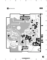
MOTHER UNIT

SIDE B

1

1

Summary of Contents for gM-2037ZF

Page 1: ...ER ELECTRONICS ASIACENTRE PTE LTD 253 Alexandra Road 04 01 Singapore 159936 C PIONEER CORPORATION 2003 K ZZB JUNE 2003 Printed in Japan ORDER NO CRT3066 SUB WOOFER AMPLIFIER GM 2037ZFX1R UC Service Manual GM 2037ZF X1R UC For details refer to Important symbols for good services VEHICLE DESTINATION PRODUCED AFTER FORD PART No ID No PIONEER MODEL No RANGER North America August 2003 4L5T 18C808 AB GM...

Page 2: ...r glue to proper portions by the appropriate amount For replacement parts or tools the prescribed ones should be used 4 Shipping mode and shipping screws To protect the product from damages or failures that may be caused during transit the shipping mode should be set or the shipping screws should be installed before shipping out in accordance with this manual if necessary 1 Product safety You shou...

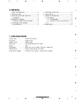
Page 3: ...T 10 6 ADJUSTMENT 11 7 GENERAL INFORMATION 11 7 1 DIAGNOSIS 11 7 1 1 DISASSEMBLY 11 7 1 2 CONNECTOR FUNCTION DESCRIPTION 12 7 2 IC 13 8 OPERATIONS 13 1 SPECIFICATIONS Power source 14 4 0 2V 10 6 16 0V Grounding Negative type Backup current 0 5mA or less Dimensions 164mm W x44mm H x117mm D Weight 476g Rated power 35W or less 1 5Ω f 100Hz THD N 2 80kHz LPF Residual noise 0 5mV or more Rg 1k ohm IHF ...

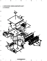
Page 4: ...4 1 2 3 4 1 2 3 4 F E D C B A GM 2037ZF X1R UC 2 EXPLODED VIEWS AND PARTS LIST 2 1 EXTERIOR 5 3 3 3 11 4 10 6 12 2 8 4 4 1 7 9 13 14 14 14 14 14 A ...

Page 5: ...nector CN102 HKE0039 12 IC IC200 PAL006A 13 Cushion HNM0145 14 Cushion HNM6623 Mark No Description Part No EXTERIOR SECTION PARTS LIST NOTE Parts marked by are generally unavailable because they are not in our Master Spare Parts List Screws adjacent to mark on the product are used for disassembly For the applying amount of lubricants or glue follow the instructions in this manual In the case of no...

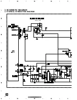
Page 6: ...3 SCHEMATIC DIAGRAM 3 1 OVERALL CONNECTION DIAGRAM A GAIN 2 3dB 6 1 2 3 4 1 2 3 4 F E D C B A GM 2037ZF X1R UC ...

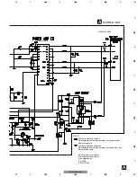
Page 7: ...nd capacitor fixed values are expressed as 2 2 2R2 0 022 R022 Symbol indicates a resistor No differentiation is made between chip resistors and discrete resistors NOTE Symbol indicates a capacitor No differentiation is made between chip capacitors and discrete capacitors GAIN 26dB GAIN 23 7dB ...

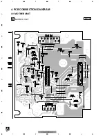
Page 8: ...8 1 2 3 4 1 2 3 4 F E D C B A GM 2037ZF X1R UC 4 PCB CONNECTION DIAGRAM 4 1 MOTHER UNIT A A MOTHER UNIT SIDE A 1 2 3 4 5 6 10 9 8 7 6 5 4 3 2 1 ...

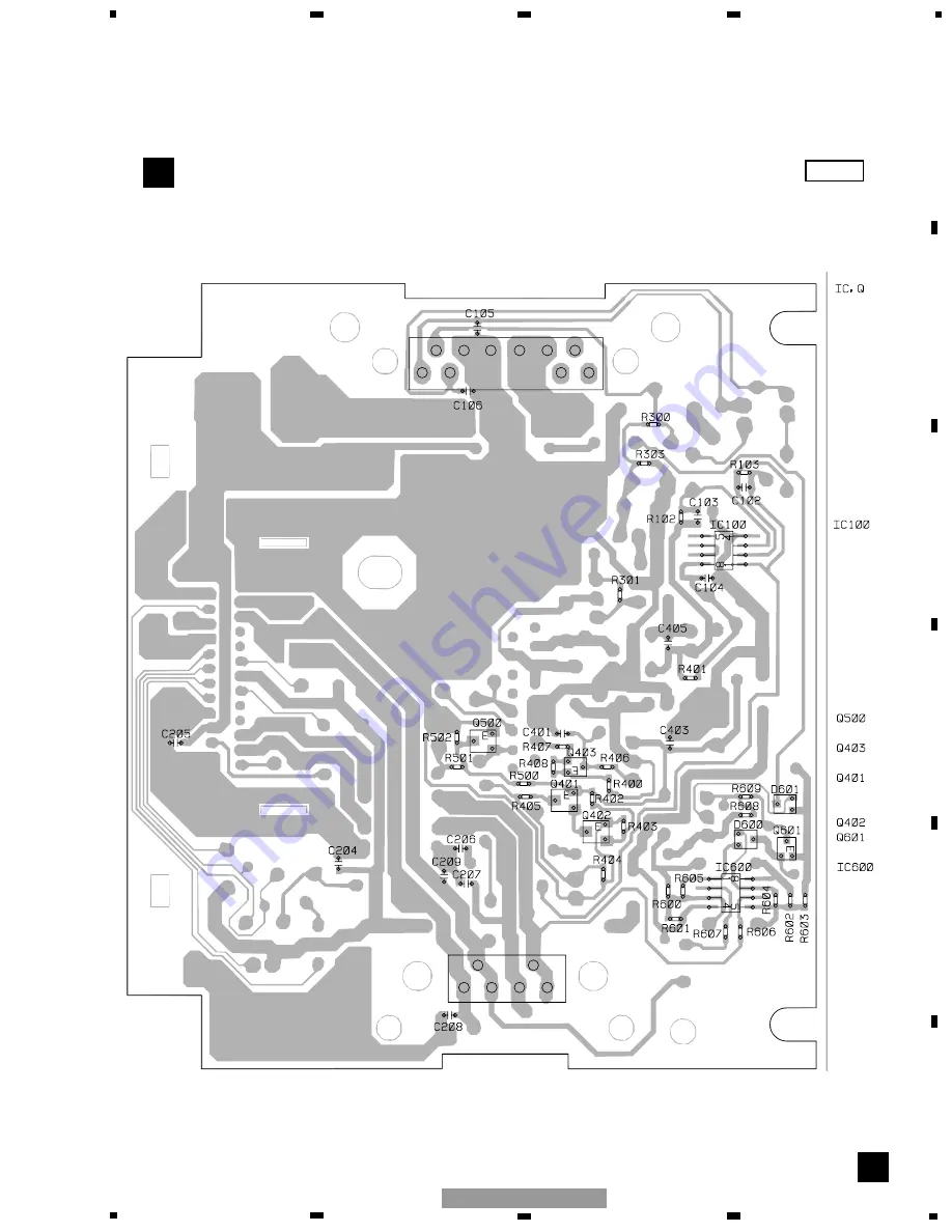
Page 9: ...9 5 6 7 8 F E D C B A 5 6 7 8 GM 2037ZF X1R UC A A MOTHER UNIT SIDE B 1 1 ...

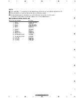
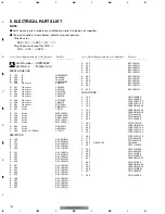
Page 10: ... RESISTORS R 100 RD1 4PU432J R 101 RD1 4PU432J R 102 RS1 16S332J R 103 RS1 16S332J R 300 RS1 16S103J R 301 RS1 16S472J R 302 RD1 4PU472J R 303 RS1 16S332J R 307 RD1 4PU102J R 400 RS1 16S222J R 401 RS1 16S102J R 402 RS1 16S103J R 403 RS1 16S103J R 404 RS1 16S103J R 405 RS1 16S103J R 406 RS1 16S101J R 407 RS1 16S103J R 408 RS1 16S103J R 500 RS1 16S103J R 501 RS1 16S331J R 502 RS1 16S103J R 600 RS1 1...

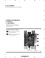
Page 11: ...n this chapter 7 GENERAL INFORMATION 7 1 DIAGNOSIS 7 1 1 DISASSEMBLY 1 1 2 Removing the Mother Unit Fig 1 Remove the four screws and then remove the Heat Sink Remove the three screws and then remove the Mother Unit Fig 1 Heat Sink Mother Unit 1 Remove the Case Removing the Case not shown 1 1 1 2 2 2 ...

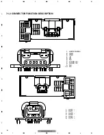
Page 12: ... 3 4 F E D C B A GM 2037ZF X1R UC 7 1 2 CONNECTOR FUNCTION DESCRIPTION 1 2 3 4 5 6 7 8 9 10 1 2 3 4 5 6 1 AMP ENABLE 2 GND 3 GND 4 B 5 B 6 NC 7 AUDIO IN 8 AUDIO IN 9 NC 10 NC 1 OUT1 2 OUT1 3 OUT2 4 OUT2 5 OUT1 6 OUT2 ...

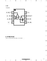
Page 13: ...13 5 6 7 8 F E D C B A 5 6 7 8 GM 2037ZF X1R UC 7 2 IC 8 OPERATIONS There is no information to be shown in this chapter 1 3 2 A OUT A IN A IN V B IN B IN B OUT V 4 5 6 7 8 NJM2068M ...

Reviews: