background image

12

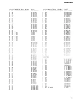
GM-222

GM-222/X1R/UC

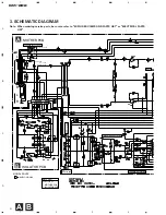
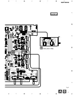
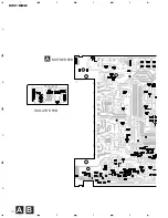
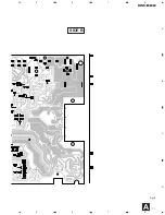
AMP UNIT

Consists of

MOTHER PCB

ISOLATOR PCB

Unit Number : HWH0062
Unit Name

: Amp Unit

MISCELLANEOUS

IC

451

IC

UPC4570HA

IC

551

IC

UPC4570C

IC

651

IC

TA8194Z

IC

851

IC

UPC4570C

IC

852

IC

UPC4570C

IC

901

IC

UPC494C

Q

551

Transistor

2SA1145

Q

552

Transistor

2SA1145

Q

553

Transistor

2SC2705

Q

554

Transistor

2SC2705

Q

555

Transistor

2SD2343

Q

556

Transistor

2SD2343

Q

561

Transistor

2SD2438

Q

562

Transistor

2SD2438

Q

563

Transistor

2SB1587

Q

564

Transistor

2SB1587

Q

651

Transistor

2SD1768S

Q

652

Transistor

2SD1768S

Q

653

Chip Transistor

2SA1162

Q

654

Transistor

2SC2458

Q

655

Transistor

2SC2458

Q

656

Transistor

2SC2458

Q

657

Transistor

2SA1048

Q

658

Transistor

2SC2458

Q

659

Transistor

2SA1048

Q

660

Transistor

2SB1243

Q

661

Transistor

2SC2712

Q

662

Transistor

2SC2712

Q

663

Chip Transistor

2SA1162

Q

901

Transistor

2SC2458

Q

902

Transistor

2SA1048

Q

903

Transistor

2SA1048

Q

904

Transistor

2SA1048

Q

905

FET

IRFIZ44N

Q

906

FET

IRFIZ44N

Q

907

Transistor

2SD1864

Q

908

Transistor

2SB1243

D

651

Diode

1SS133

D

652

Diode

1SS133

D

653

Diode

1SS133

D

654

Diode

HZS7L(B2)

D

655

Diode

1SS133

D

656

Diode

HZS7L(A2)

D

657

Diode

1SS133

D

658

Diode

1SS133

D

901

LED

BR4361F

D

902

Diode

ERA15-02VH

D

903

Diode

ERA15-02VH

D

904

Diode

HZS18L(3)

D

905

Diode

1SS133

D

906

Diode

1SS133

D

907

Diode

ESAC25M-02C

D

908

Diode

HZS16L(1)

D

909

Diode

HZS16L(1)

D

910

Diode

ESAC25M-02N

D

911

Diode

1SS133

L

851

Ferri-Inductor

CTF1007

L

852

Ferri-Inductor

CTF1007

L

901

Choke Coil 50H

CTH1142

T

901

Transformer

CTT1034

TH

901

Thermistor

CCX1013

TH

902

Thermistor

CCX1035

VR

453

Volume 10k

(A)

CCS1241

EF

902

Capacitors

CCG-081

EF

903

Capacitors

CCG-081

RESISTORS

R

137

RS1/10S222J

R

138

RS1/10S222J

R

147

RS1/8S0R0J

R

148

RS1/8S0R0J

R

455

RS1/10S0R0J

R

456

RS1/10S0R0J

R

465

RS1/8S181J

R

466

RS1/10S181J

R

501

RD1/4PU221J

R

502

RD1/4PU221J

R

551

RS1/10S222J

R

552

RS1/10S222J

R

555

RS1/10S822J

R

556

RS1/10S822J

R

557

RS1/10S471J

R

558

RS1/10S471J

R

559

RS1/10S223J

R

560

RS1/10S223J

R

561

RS1/10S153J

R

562

RD1/4PU153J

R

563

RS1/10S153J

R

564

RD1/4PU153J

R

565

RD1/4PU561J

R

566

RD1/4PU561J

R

567

RD1/4PU561J

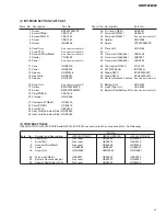
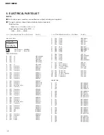
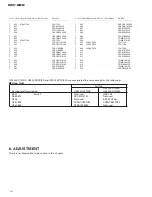
5. ELECTRICAL PARTS LIST

NOTE:

-

Parts whose parts numbers are omitted are subject to being not supplied.

-

The part numbers shown below indicate chip components.

Chip Resistor

RS1/

_

S

___

J,RS1/

__

S

___

J

Chip Capacitor (except for CQS.....)

CKS....., CCS....., CSZS.....

=====Circuit Symbol and No.===Part Name

Part No.

---

------

---------------------------------------------

-------------------------

=====Circuit Symbol and No.===Part Name

Part No.

---

------

---------------------------------------------

-------------------------

A

Summary of Contents for GM-222

Page 1: ...the safety and reliability of the product and may void the warranty If you are not qualified to perform the repair of this product properly and safely you should mot risk trying to do so and refer the repair to a qualified service technician UC model CAUTION This service manual is intended for qualified service technicians it is not meant for the casual do it yourselfer Qualified technicians have ...

Page 2: ...rast table 2 8 Cord Assy See Contrast table 2 9 1 Owner s Manual See Contrast table 2 9 2 Owner s Manual See Contrast table 2 9 3 Card See Contrast table 2 9 4 Warranty Card See Contrast table 2 1 PACKING SECTION PARTS LIST Mark No Description Part No Mark No Description Part No NOTE Parts marked by are generally unavailable because they are not in our Master Spare Parts List Screws adjacent to ma...

Page 3: ... HHG0140 7 Terminal HKC0003 x8 HKC0003 x4 HKC0003 x4 8 Cord Assy Not used HDE4453 HDE4453 9 1 Owner s Manual HRD0046 HRD0045 HRD0047 9 2 Owner s Manual Not used HRD0049 Not used 9 3 Card ARY1048 Not used Not used 9 4 Warranty Card Not used Not used HRY1087 Owner s Manual Model Part No Language GM X222 X1R UC HRD0046 English French GM X222 X1R ES HRD0045 English Spanish HRD0049 Arabic Portuguese B ...

Page 4: ...4 GM 222 2 2 EXTERIOR Fig 2 ...

Page 5: ...3 32 33 Transistor Q561 562 2SD2438 34 Transistor Q563 564 2SB1587 35 Transistor Q555 556 2SD2343 36 Thermistor TH901 CCX1013 37 FET Q905 906 IRFIZ44N 38 Diode D907 ESAC25M 02C 39 Diode D910 ESAC25M 02N 40 System Remote Control See Contrast table 2 41 Badge Unit HXA0164 42 Light Pipe Unit HXA0182 43 Special Red Battery Wire See Contrast table 2 1 EXTERIOR SECTION PARTS LIST Mark No Description Par...

Page 6: ... 15 REGULATOR 15 REGULATOR SWITCHING REGULATOR MUTE C851 852 UC 100P ES EW 470P THERMO DETECTION L R R L AMP UNIT Consists of MOTHER PCB ISOLATOR PCB AUDIO SIGNAL SIGNAL ROUTE 3 SCHEMATIC DIAGRAM Note When ordering service parts be sure to refer to EXPLODED VIEWS AND PARTS LIST or ELECTRICAL PARTS LIST A B ...
Page 7: ...15 15A ES and EW models only ES and EW models only MUTE BUFFER AMP PRE DRIVER POWER AMP OVER CURRENT DETECTOR SWITCHING CONTROL OVER VOLTAGE PROTECTOR POWER CONTROL MUTE OVER CURRENT DETECTOR GROUND WIRE BATTERY WIRE SYSTEM REMOTE CONTROL Fig 3 A ...

Page 8: ...onnector P C Board Chip Part SIDE A SIDE B NOTE FOR PCB DIAGRAMS 1 The parts mounted on this PCB include all necessary parts for several destination For further information for respective destinations be sure to check with the schematic dia gram 2 Viewpoint of PCB diagrams A MOTHER PCB ...

Page 9: ...9 GM 222 5 6 7 8 A B C D 5 6 7 8 Fig 4 SIDE A B A OUT IN B ISOLATOR PCB ...

Page 10: ...10 GM 222 A 1 2 3 4 B C D 1 2 3 4 A MOTHER PCB ISOLATOR PCB A B ...

Page 11: ...11 GM 222 5 6 7 8 A B C D 5 6 7 8 Fig 5 SIDE B A ...

Page 12: ... 656 Diode HZS7L A2 D 657 Diode 1SS133 D 658 Diode 1SS133 D 901 LED BR4361F D 902 Diode ERA15 02VH D 903 Diode ERA15 02VH D 904 Diode HZS18L 3 D 905 Diode 1SS133 D 906 Diode 1SS133 D 907 Diode ESAC25M 02C D 908 Diode HZS16L 1 D 909 Diode HZS16L 1 D 910 Diode ESAC25M 02N D 911 Diode 1SS133 L 851 Ferri Inductor CTF1007 L 852 Ferri Inductor CTF1007 L 901 Choke Coil 50H CTH1142 T 901 Transformer CTT10...

Page 13: ...5 RN1 10SE1002D R 856 RN1 10SE1002D R 857 RN1 10SE1002D R 858 RN1 10SE1002D R 859 RN1 10SE1002D R 860 RN1 10SE1002D R 861 RN1 10SE1002D R 862 RN1 10SE1002D R 864 RS1 10S104J R 868 RS1 10S104J R 869 RD1 4PU473J R 872 RD1 4PU473J R 901 RS1 2PMF561J R 902 RS1 2PMF220J R 903 RD1 4PU102J R 904 RD1 4PU102J R 905 RS1 10S472J R 906 RS1 10S103J R 907 RS1 10S183J R 908 RD1 4PU100J R 909 RD1 4PU100J R 910 RS...

Page 14: ...06 CQMA472J50 C 907 3300µF 16V CCH1130 C 908 3300µF 35V CCH1200 C 909 3300µF 35V CCH1200 C 910 CEAS101M35 C 911 CEAS101M35 C 912 CEAS100M50 C 913 CEAS100M50 C 914 CQMA102J50 C 915 CQMA102J50 C 916 CFTNA224J50 C 917 CQMA102J50 C 918 CKSYB103K50 Circuit Symbol and No Part Name Part No Circuit Symbol and No Part Name Part No 6 ADJUSTMENT There is no information to be shown in this chapter GM 222 X1R ...

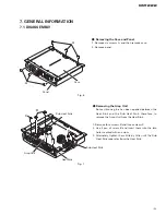
Page 15: ...etween the Heat Sink and the Sub Heat Sink therefore to remove the Amp Unit from the Heat Sink 1 Remove four screws B and three screws C 2 Use 2 pcs of screw B and insert them into the two holes marked with an arrow 3 Alternately tighten them little by little until the Sub Heat Sink separates from the Heat Sink A A B B C C Panel Case Sub Heat Sink Sub Heat Sink Heat Sink Amp Unit Fig 6 Fig 7 ...

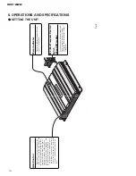
Page 16: ...clockwise Set the gain control to NORMAL when this amplifier is connected to a Pioneer car stereo with RCA output jacks If the sound is too low or distorts adjust the gain con trol Power Indicator The power indicator lights when the power is switched on BFC Beat Frequency Control Switch ES and EW models If you hear a beat while listening to an AM broadcast with your car stereo change the BFC switc...

Page 17: ... control terminal connect the male terminal to the power terminal through the ignition switch Fuse 30 A Grommet Special red battery wire After making all other connections at the amplifier connect the battery wire terminal of the amplifier to the positive terminal of the battery Ground wire black Connect to metal body or chassis Fuse 20 A Car stereo with RCA output jacks External Output Connecting...

Page 18: ...t the speaker leads to suit the mode Connect the speakers according to figures on the fol lowing pages When connecting to the speaker input do not connect the RCA output When connecting to the RCA input do not connect the speaker input Two channel mode stereo One channel mode mono Three channel mode stereo mono The power amplifier is basically a two channel one channel bridgeable amplifier but thr...

Page 19: ...put UC and ES models 35 W 2 at 14 4V 4 Ω 20 20 000 Hz 0 08 THD 80 W 1 at 14 4V 4 Ω 20 20 000 Hz 0 8 THD 50 W 2 at 14 4V 2 Ω 20 20 000 Hz 0 8 THD Continuous power output EW model 55 W 2 125 W 1 DIN45324 B 14 4 V Load impedance 4 Ω 2 8 Ω allowable Bridge connection 4 8 Ω allowable Frequency response 10 50 000 Hz 0 dB 1 dB Signal to noise ratio UC and ES models 105 dB IHF A network Signal to noise ra...

Reviews: