18
GM-222
•
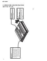
Be sure to use the special red battery wire
supplied with the amplif
ier and connect directly to
the battery
. Use the supplied black ground wire
and connect to the v
ehicle body
.
1.
P
ass the battery wir
e fr
om the
engine compartment to the interior
of the v
ehicle.
•
After making all other connections to the
amplif
ier
,
connect the battery wire terminal of
the amplif
ier to the positi
v
e (+) terminal of
the battery
.
2.
Connect the wir
es to the terminal.
•
Fix the wires securely with the terminal
scre
ws.
1.
Expose the end of the speak
er wir
es
by about 10 mm and twist it using
nippers or a cutter
.
2.
Attach lugs to speak
er wir
e ends.
•
Use pliers,
etc.,
to crimp lugs to wires.
3.
Connect the speak
er wir
es to the
speak
er terminals.
•
F
ix the speak
er wires securely with the termi-
nal scre
ws.
UC model:
ES and EW models:
10
mm
Fuse (30A)
Engine
compart-
ment
Interior of
the v
ehicle
Drill an 8-mm
hole into the
v
ehicle body
.
Insert the O-ring rubber
grommet into the v
ehicle
body
.
Positi
v
e terminal
GND terminal
Po
wer terminal
Battery wire
System remote
control terminal
System remote
control wire
(Blue)
Ground wire
T
wist
Speak
er output
terminal
Speak
er wire
T
erminal scre
w
Speak
er wire
Lug
Speak
er output
terminal
Speak
er wire
T
erminal scre
w
Speak
er input
terminal
-
CONNECTING
THE POWER TERMINAL
-
CONNECTING
THE SPEAKER TERMINALS
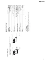
The speak
er output mode can be tw
o-chan-
nel (stereo),
one-channel (mono),
or three-
channel ( mono).
T
o
connect the
speak
er leads to suit the mode. Connect the
speak
ers according to f
igures on the fol-
lo
wing pages.
•
When connecting to the speak
er input,
do not
connect the RCA output.
•
When connecting to the RCA input,
do not
connect the speak
er input.
T
wo-channel mode (stereo)
One-channel mode (mono)
Three-channel mode ( mono)
The po
wer amplif
ier is basically a tw
o-
channel/one-channel bridgeable amplif
ier
,
b
ut three channels can be achie
v
ed by
combining the stereo and mono modes
using inductors and capacitors.
Thr
ee-channel mode,
tw
o-way system
Thr
ee-channel mode,
thr
ee-way system
•
The inductor (L1 or L2 in the diagram)
acts as a lo
w-pass f
ilter
.
The capacitor
(C1 or C2 in the diagram) acts as a high-
pass f
ilter
.
The inductor (L)
shall be used
on the w
oofer/sub-w
oofer
,
and that a
capacitor (C) shall be used on the
high/mid-high.
•
Remember when bridging an amplif
ier it
will see only half of the original speak
er
impedance. Therefore,
you
must
use
speak
ers that ha
v
e ratings of 4 ohms or
higher
. If you use speak
ers that ha
v
e
lo
wer impedance ratings it may cause
damage to the amplif
ier
.
•
When the inductors and capacitors are
connected to the speak
er wires,
secure or
solder them so the
y cannot be pulled
loose.
T
ape or use heat shrink on the
joints to pre
v
ent short circuits.
C2
C2
L1
L2
L2
C1
C1
C1
L1
(Right)
Speak
er input
(Left)
(Left)
Speak
er
(Right)
(Right)
Speak
er input
(Left)
Speak
er
(Mono)
Mid-high (Left)
W
oofer (Mono)
Mid-high (Right)
High/mid-high
(Left)
Mid/mid-bass
(Left)
W
oofer/sub-w
oofer
(Mono)
Mid/mid-bass
(Right)
High/mid-high
(Right)
-
CONNECTING THE SPEAKER WIRES
(1) UC model
Fig. 11
Fig. 12
Fig. 13
Fig. 14
Fig. 15
Fig. 16
Fig. 17
Fig. 18
Fig. 19
Fig. 20

