background image

PIONEER CORPORATION

4-1, Meguro 1-Chome, Meguro-ku, Tokyo 153-8654, Japan 

PIONEER ELECTRONICS (USA) INC.

P.O.Box 1760, Long Beach, CA 90801-1760 U.S.A.

PIONEER EUROPE NV

Haven 1087 Keetberglaan 1, 9120 Melsele, Belgium 

PIONEER ELECTRONICS ASIACENTRE PTE.LTD.

253 Alexandra Road, #04-01, Singapore 159936

PIONEER CORPORATION 2004

K-ZZB. MAR. 2004 Printed in Japan

ORDER NO.

CRT3241

BRIDGEABLE FOUR-CHANNEL POWER AMPLIFIER

GM-4000F

X1R/EW

Service
Manual

GM-4000F/X1R/EW

GM-4000F

X1R/UC

For details, refer to "Important symbols for good services". 

GM-4000F

X1R/ES

Summary of Contents for GM-4000F/X1R/ES

Page 1: ...087 Keetberglaan 1 9120 Melsele Belgium PIONEER ELECTRONICS ASIACENTRE PTE LTD 253 Alexandra Road 04 01 Singapore 159936 C PIONEER CORPORATION 2004 K ZZB MAR 2004 Printed in Japan ORDER NO CRT3241 BRIDGEABLE FOUR CHANNEL POWER AMPLIFIER GM 4000FX1R EW Service Manual GM 4000F X1R EW GM 4000FX1R UC For details refer to Important symbols for good services GM 4000FX1R ES ...

Page 2: ...ing mode should be set or the shipping screws should be installed before shipping out in accordance with this manual if necessary 1 Product safety You should conform to the regulations governing the product safety radio and noise and other regulations and should keep the safety during servicing by following the safety instructions described in this manual SAFETY INFORMATION UC model CAUTION This s...

Page 3: ...sions 300 W 61 H 237 D mm Weight 3 8 kg Leads for wiring not included Maximum power output 70 W 4 150 W 2 Continuous power output 45 W 4 100 W 2 DIN45324 B 14 4 V Load impedance 4 Ω 2 8 Ω allowable Bridge connection 4 8 Ω allowable Frequency response 10 50 000 Hz 0 dB 1 dB Signal to noise ratio 100 dB IEC A network Distortion 0 008 10 W 1 kHz Separation 60 dB 1 kHz Low pass filter Cut off frequenc...

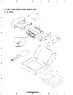
Page 4: ...4 1 2 3 4 1 2 3 4 F E D C B A GM 4000F X1R EW 2 EXPLODED VIEWS AND PARTS LIST 2 1 PACKING ...

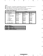
Page 5: ... HHP0251 HHP0251 10 1 Owner s Manual HRD0268 HRD0267 HRD0269 10 2 Owner s Manual Not used Not used HRD0270 10 3 Warranty Card HRY1157 ARY1048 Not used PACKING SECTION PARTS LIST NOTE Parts marked by are generally unavailable because they are not in our Master Spare Parts List Screws adjacent to mark on the product are used for disassembly For the applying amount of lubricants or glue follow the in...

Page 6: ...A 6 1 2 3 4 1 2 3 4 F E D C B A GM 4000F X1R EW 2 2 EXTERIOR ...

Page 7: ...HNR0282 19 Spacer HNV0016 20 Fuse 25A HEK0025 21 Amp Unit EW HWH0246 Amp Unit UC HWH0247 Amp Unit ES HWH0248 22 Pin Jack CN802 HKB0001 23 Pin Jack CN801 HKB0005 24 Terminal CN851 HKE0033 25 Terminal CN901 HKE0036 26 Terminal CN903 HKF0001 27 Terminal CN904 HKF0001 28 Connector CN803 HKM1077 29 Connector CN804 HKM1077 30 Buss Bar HNC0043 31 Clip HNC0054 32 Holder HNC0082 33 Screw PPZ30P100SAD 34 Li...

Page 8: ... SCH diagram Guide page Detailed page Note When ordering service parts be sure to refer to EXPLODED VIEWS AND PARTS LIST or ELECTRICAL PARTS LIST A a A 8 1 2 3 4 1 2 3 4 F E D C B A GM 4000F X1R EW 3 SCHEMATIC DIAGRAM 3 1 OVERALL CONNECTION DIAGRAM GUIDE PAGE ...

Page 9: ...nent parts indicates the importance of the safety factor of the part Therefore when replacing be sure to use parts of identical designation Symbol indicates a resistor No differentiation is made between chip resistors and discrete resistors NOTE Symbol indicates a capacitor No differentiation is made between chip capacitors and discrete capacitors A AMP UNIT FUSE HEK0025 ...

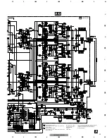
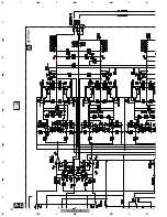
Page 10: ...10 1 2 3 4 1 2 3 4 F E D C B A GM 4000F X1R EW A a A b A a A a A b 1 ...

Page 11: ...11 5 6 7 8 F E D C B A 5 6 7 8 GM 4000F X1R EW A a A b A a A a A b 2 3 4 ...

Page 12: ...12 1 2 3 4 1 2 3 4 F E D C B A GM 4000F X1R EW A a A b A b 1 A AMP UNIT ...

Page 13: ...n some component parts indicates the importance of the safety factor of the part Therefore when replacing be sure to use parts of identical designation Symbol indicates a resistor No differentiation is made between chip resistors and discrete resistors NOTE Symbol indicates a capacitor No differentiation is made between chip capacitors and discrete capacitors FUSE HEK0025 ...

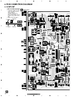
Page 14: ...all necessary parts for several destination For further information for respective destinations be sure to check with the schematic dia gram 2 Viewpoint of PCB diagrams 1 2 3 4 BR BR BL BL 1 2 3 4 AR AR AL AL BL BR INPUT INPUT AL AR AL AR OUTPUT 14 1 2 3 4 1 2 3 4 F E D C B A GM 4000F X1R EW 4 PCB CONNECTION DIAGRAM 4 1 AMP UNIT ...

Page 15: ...15 5 6 7 8 F E D C B A 5 6 7 8 GM 4000F X1R EW A SIDE A 1 2 3 1 2 3 1 2 3 1 2 3 B GND REM 1 2 3 1 2 3 4 5 6 7 8 BFC ...

Page 16: ...16 1 2 3 4 1 2 3 4 F E D C B A GM 4000F X1R EW A A AMP UNIT 1 1 ...

Page 17: ...17 5 6 7 8 F E D C B A 5 6 7 8 GM 4000F X1R EW A SIDE B 1 1 ...

Page 18: ...istor 2SC2458 Q 657 Transistor 2SA1048 Q 658 Transistor 2SB1243 Q 951 Transistor DTA114ES Q 952 Transistor 2SD1919 Q 953 Transistor 2SB1277 Q 954 Transistor 2SB1277 Q 955 Transistor 2SD1919 Q 956 FET IRF1010N Q 957 FET IRF1010N Q 958 FET IRF1010N Q 959 FET IRF1010N Q 960 Transistor 2SD2395 Q 961 Transistor 2SB1566 Q 962 Transistor DTC114TK Q 963 Transistor 2SC2412K D 601 Diode 1SS133 D 602 Diode 1...

Page 19: ...R 355 RD1 4PU153J R 356 RD1 4PU153J R 357 RD1 4PU561J R 358 RD1 4PU561J R 359 RD1 4PU161J R 360 RD1 4PU161J R 361 RD1 4PU473J R 362 RD1 4PU473J R 363 RD1 4PU221J R 364 RD1 4PU562J R 365 RD1 4PU222J R 366 RD1 4PU473J R 367 RD1 4PU473J R 368 0 22Ω HCN0001 R 369 0 22Ω HCN0001 R 370 0 22Ω HCN0001 R 371 0 22Ω HCN0001 R 372 RS1 2PMF100J R 402 RS1 16S912J R 403 RS1 16S103J R 404 RS1 16S123J R 405 RS1 16S...

Page 20: ...2J R 967 RS1 16S272J R 968 RD1 4PU272J R 970 RS1 16S472J R 971 RS1 16S472J R 972 RS1 2PMF121J R 973 RS1 2PMF121J R 974 RS1 2PMF121J R 975 RS1 2PMF121J R 976 RS1 2PMF220J R 977 RS1 2PMF220J R 978 RS1 2PMF220J R 980 RS1 2PMF100J R 981 RS1 2PMF100J R 982 RD1 4PU222J R 983 RD1 4PU222J R 984 RD1 4PU103J R 985 RD1 4PU104J R 986 RD1 4PU153J R 990 RS1 16S222J CAPACITORS C 102 CFTLA274J50 C 103 CFTLA154J50...

Page 21: ...50 C 811 CFTLA103J50 C 812 CFTLA103J50 C 831 CEAT100M16 C 832 CEAT100M16 C 833 CEAT100M16 C 834 CEAT100M16 C 851 CKSQYB471K50 C 852 CKSQYB471K50 C 853 CEAT100M16 C 854 CEAT100M16 C 855 CQMA472J50 C 856 CQMA472J50 C 857 CCSQCH470J50 C 858 CCSQCH470J50 C 859 CCSQCH470J50 C 860 CCSQCH470J50 C 861 CFTLA103J50 C 862 CFTLA103J50 C 901 CFTNA334J50 C 902 CFTLA103J50 C 951 CEAT100M16 C 952 CEAT221M10 C 953...

Page 22: ... Fig 2 Case 2 Remove the two screws 3 Remove the six screws and then remove the Panel 2 Remove the six screws and then remove the Case 1 1 1 2 2 2 2 2 2 4 Remove the two screws 5 Remove the eighteen screws 6 Remove the twelve screws and then remove the Amp Unit 1 1 1 1 1 1 2 2 3 3 3 3 3 3 4 4 5 5 6 6 6 6 6 6 6 6 6 6 Panel Panel Amp Unit 6 6 22 1 2 3 4 1 2 3 4 F E D C B A GM 4000F X1R EW ...

Page 23: ...23 5 6 7 8 F E D C B A 5 6 7 8 GM 4000F X1R EW 7 1 2 CONNECTOR FUNCTION DESCRIPTION ...

Page 24: ...ng the speaker input terminals turn the gain control counter clockwise Power Indicator The power indicator lights when the power is switched on LPF Low Pass Filter HPF High Pass Filter Select Switch Set the LPF HPF select switch as follows according to the type of speaker that is connected to the speaker output connector and the car stereo system LPF HPF Select Audio frequency range Speaker Remark...

Reviews: