GM-520T/XU/UC
12
1
2
3
4
1
2
3
4
C
D
F
A
B
E
A-a
A-b
A-a
A-a
A-b
1
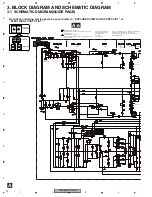
Decimal points for resistor
and capacitor fixed values
are expressed as :
2.2 2R2
0.022 R022
←
←
The
>
mark found on some component parts indicates
the importance of the safety factor of the part.
Therefore, when replacing, be sure to use parts of
identical designation.
Symbol indicates a resistor.
No differentiation is made between chip resistors and
discrete resistors.
NOTE :
Symbol indicates a capacitor.
No differentiation is made between chip capacitors and
discrete capacitors.
BASS BOOST
GAIN
BASS BOOST
GAIN
0dB
0dB
+18.5dBs
(BB ON
INPUT MAX)
0dB
-1.7dB ~
-32.1dB
0dB or +12dB or +6dB
+18.3dBs
-13.8dBs
-1.8dBs
+18.3dBs
Summary of Contents for GM-520T
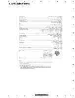
Page 5: ...GM 520T XU UC 5 5 6 7 8 5 6 7 8 C D F A B E 1 SPECIFICATIONS ...
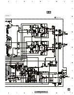
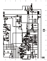
Page 13: ...GM 520T XU UC 13 5 6 7 8 5 6 7 8 C D F A B E A a A b A a A a A b 2 3 4 BASS BOOST GAIN ...
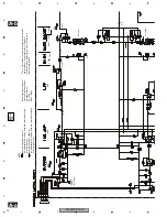
Page 15: ...GM 520T XU UC 15 5 6 7 8 5 6 7 8 C D F A B E A a A b A b 2 3 4 47K 47K 8R2K 8R2K ...
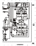
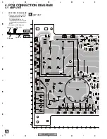
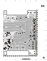
Page 18: ...GM 520T XU UC 18 1 2 3 4 1 2 3 4 C D F A B E A A AMP UNIT R L R L Lch Rch ...
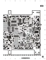
Page 19: ...GM 520T XU UC 19 5 6 7 8 5 6 7 8 C D F A B E A SIDE B 1 1 1 ...
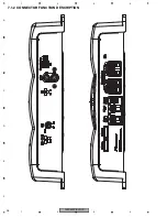
Page 26: ...GM 520T XU UC 26 1 2 3 4 1 2 3 4 C D F A B E 7 1 2 CONNECTOR FUNCTION DESCRIPTION ...
Page 27: ...GM 520T XU UC 27 5 6 7 8 5 6 7 8 C D F A B E 8 OPERATIONS ...
Page 28: ...GM 520T XU UC 28 1 2 3 4 1 2 3 4 C D F A B E ...
Page 29: ...GM 520T XU UC 29 5 6 7 8 5 6 7 8 C D F A B E ...

