background image

19

5

6

7

8

F

E

D

C

B

A

5

6

7

8

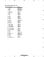
GM-6000F/X1R/EW

D

613

Diode

HZS16L(1)

D

662

Diode

ERA15-02VH

D

663

Diode

ERA15-02VH

D

701

Diode

1SS133

D

901

Diode

1SS133

D

902

Diode

1SS133

D

903

Diode

1SS133

D

904

Diode

1SS133

D

909

Diode

1SS133

D

910

LED

DB1112H

L

602

Choke Coil 75µH

HTH0021

L

603

Choke Coil 75µH

HTH0021

L

851

Ferri-Inductor

CTF1007

L

852

Ferri-Inductor

CTF1007

L

853

Ferri-Inductor

CTF1007

L

854

Ferri-Inductor

CTF1007

T

601

Transformer

HTT0034

TH

601

Thermistor

HCX0002

TH

602

Thermistor

HCX0002

TH

603

Thermistor

HCX0001

S

101

Switch(A LPF/HPF)

HSH0005

S

102

Switch(B LPF/HPF)

HSH0005

S

601

Switch(BFC)(EW,ES)

HSH-156

S

851

Switch(2CH/4CH)

HSH0006

VR

121

Volume

HCS0007

VR

122

Volume

HCS0007

VR

201

Volume

HCS0006

VR

202

Volume

HCS0006

RESISTORS

R

101

RS1/16S103J

R

102

RS1/16S103J

R

103

RS1/16S103J

R

104

RS1/16S103J

R

105

RS1/16S103J

R

106

RS1/16S103J

R

107

RS1/16S103J

R

108

RS1/16S103J

R

109

RS1/16S103J

R

110

RS1/16S103J

R

111

RS1/16S103J

R

112

RS1/16S103J

R

113

RS1/16S472J

R

114

RS1/16S472J

R

115

RS1/16S472J

R

116

RS1/16S472J

R

117

RS1/16S103J

R

118

RS1/16S103J

R

119

RS1/16S103J

R

120

RS1/16S103J

R

121

RS1/16S562J

R

122

RS1/16S562J

R

123

RS1/16S562J

R

124

RS1/16S562J

R

125

RS1/16S822J

R

126

RS1/16S822J

R

127

RS1/16S822J

R

128

RS1/16S822J

R

129

RS1/16S103J

R

130

RS1/16S103J

R

131

RS1/16S103J

R

132

RS1/16S103J

R

133

RS1/16S822J

R

134

RS1/16S822J

R

135

RS1/16S822J

R

136

RS1/16S822J

R

139

RS1/16S222J

R

140

RS1/16S222J

R

141

RS1/16S222J

R

142

RS1/16S222J

R

201

RD1/4PU472J

R

202

RD1/4PU472J

R

203

RD1/4PU472J

R

204

RD1/4PU472J

R

207

RD1/4PU223J

R

208

RD1/4PU223J

R

211

RD1/4PU111J

R

212

RD1/4PU111J

R

213

RD1/4PU111J

R

214

RD1/4PU111J

R

301

RD1/4PU103J

R

302

RD1/4PU103J

R

303

RD1/4PU103J

R

304

RD1/4PU103J

R

305

RD1/4PU333J

R

306

RD1/4PU333J

R

307

RD1/4PU333J

R

308

RD1/4PU333J

R

309

RD1/4PU391J

R

310

RD1/4PU391J

R

311

RD1/4PU391J

R

312

RD1/4PU391J

R

317

RD1/4PU331J

R

318

RD1/4PU331J

R

319

RD1/4PU331J

R

320

RD1/4PU331J

R

321

RD1/4PU331J

R

322

RD1/4PU331J

R

323

RD1/4PU331J

R

324

RD1/4PU331J

R

325

RD1/4PU681J

R

326

RD1/4PU681J

R

327

RD1/4PU681J

R

328

RD1/4PU681J

R

329

RD1/4PU561J

R

330

RD1/4PU561J

R

331

RD1/4PU561J

R

332

RD1/4PU561J

R

333

RD1/4PU333J

R

334

RD1/4PU333J

R

335

RD1/4PU333J

R

336

RD1/4PU333J

R

337

RD1/4PU681J

R

338

RD1/4PU681J

R

339

RD1/4PU681J

R

340

RD1/4PU681J

R

341

RD1/4PU223J

R

342

RD1/4PU223J

R

343

RD1/4PU223J

R

344

RD1/4PU223J

R

349

RD1/4PU101J

R

350

RD1/4PU101J

R

351

RD1/4PU101J

R

352

RD1/4PU101J

R

353

RD1/4PU512J

R

354

RD1/4PU512J

R

355

RD1/4PU512J

R

356

RD1/4PU512J

R

357

RD1/4PU222J

R

358

RD1/4PU222J

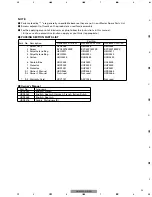
=====Circuit Symbol and No.===Part Name

Part No.

---

------

------------------------------------------

-------------------------

=====Circuit Symbol and No.===Part Name

Part No.

---

------

------------------------------------------

-------------------------

Summary of Contents for GM-6000FX1R/ES

Page 1: ...087 Keetberglaan 1 9120 Melsele Belgium PIONEER ELECTRONICS ASIACENTRE PTE LTD 253 Alexandra Road 04 01 Singapore 159936 C PIONEER CORPORATION 2004 K ZZB MAR 2004 Printed in Japan ORDER NO CRT3240 BRIDGEABLE FOUR CHANNEL POWER AMPLIFIER GM 6000FX1R EW Service Manual GM 6000F X1R EW GM 6000FX1R UC For details refer to Important symbols for good services GM 6000FX1R ES ...

Page 2: ...ing mode should be set or the shipping screws should be installed before shipping out in accordance with this manual if necessary 1 Product safety You should conform to the regulations governing the product safety radio and noise and other regulations and should keep the safety during servicing by following the safety instructions described in this manual SAFETY INFORMATION UC model CAUTION This s...

Page 3: ... 20 A 2 Dimensions 300 W 61 H 324 D mm Weight 5 2 kg Leads for wiring not included Maximum power output 100 W 4 240 W 2 Continuous power output 75 W 4 200 W 2 DIN45324 B 14 4 V Load impedance 4 Ω 2 8 Ω allowable Bridge connection 4 8 Ω allowable Frequency response 10 50 000 Hz 0 dB 1 dB Signal to noise ratio 95 dB IEC A network Distortion 0 008 10 W 1 kHz Separation 65 dB 1 kHz Low pass filter Cut...

Page 4: ...4 1 2 3 4 1 2 3 4 F E D C B A GM 6000F X1R EW 2 EXPLODED VIEWS AND PARTS LIST 2 1 PACKING ...

Page 5: ...9 1 Owner s Manual HRD0264 HRD0263 HRD0265 9 2 Owner s Manual Not used Not used HRD0266 9 3 Warranty Card HRY1157 ARY1048 Not used PACKING SECTION PARTS LIST NOTE Parts marked by are generally unavailable because they are not in our Master Spare Parts List Screws adjacent to mark on the product are used for disassembly For the applying amount of lubricants or glue follow the instructions in this m...

Page 6: ...A 6 1 2 3 4 1 2 3 4 F E D C B A GM 6000F X1R EW 2 2 EXTERIOR ...

Page 7: ...w BMZ30P050FTC 17 Insulator HNM0195 18 Heat Sink HNR0281 19 Spacer HNV0016 20 Fuse 20A HEK0020 21 Amp Unit EW HWH0243 Amp Unit UC HWH0244 Amp Unit ES HWH0245 22 Pin Jack CN852 HKB0002 23 Pin Jack CN851 HKB0006 24 Terminal CN601 HKE0020 25 Connector CN301 HKE0030 26 Terminal CN604 HKF0001 27 Clip HNC0054 28 Holder HNC0082 29 Screw PPZ30P100SAD 30 Light Pipe Unit HXA0322 31 Screw PPZ30P120FZK 32 Scr...

Page 8: ... SCH diagram Guide page Detailed page Note When ordering service parts be sure to refer to EXPLODED VIEWS AND PARTS LIST or ELECTRICAL PARTS LIST A a A 8 1 2 3 4 1 2 3 4 F E D C B A GM 6000F X1R EW 3 SCHEMATIC DIAGRAM 3 1 OVERALL CONNECTION DIAGRAM GUIDE PAGE ...

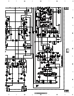
Page 9: ...e mark found on some component parts indicates the importance of the safety factor of the part Therefore when replacing be sure to use parts of identical designation Symbol indicates a resistor No differentiation is made between chip resistors and discrete resistors NOTE Symbol indicates a capacitor No differentiation is made between chip capacitors and discrete capacitors A AMP UNIT ...

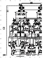
Page 10: ...10 1 2 3 4 1 2 3 4 F E D C B A GM 6000F X1R EW A a A b A a A a A b 1 ...

Page 11: ...11 5 6 7 8 F E D C B A 5 6 7 8 GM 6000F X1R EW A a A b A a A a A b 2 3 ...

Page 12: ...12 1 2 3 4 1 2 3 4 F E D C B A GM 6000F X1R EW A a A b A b 1 1 2 3 4 5 1 2 3 4 5 1 2 3 4 5 A AMP UNIT ...

Page 13: ... mark found on some component parts indicates the importance of the safety factor of the part Therefore when replacing be sure to use parts of identical designation Symbol indicates a resistor No differentiation is made between chip resistors and discrete resistors NOTE Symbol indicates a capacitor No differentiation is made between chip capacitors and discrete capacitors ...

Page 14: ... necessary parts for several destination For further information for respective destinations be sure to check with the schematic dia gram 2 Viewpoint of PCB diagrams 2 Viewpoint of PCB diagrams PREOUT L PREOUTR AL AR BL BL 1 2 3 4 9 11 10 12 3 5 4 6 14 1 2 3 4 1 2 3 4 F E D C B A GM 6000F X1R EW 4 PCB CONNECTION DIAGRAM 4 1 AMP UNIT ...

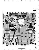
Page 15: ...15 5 6 7 8 F E D C B A 5 6 7 8 GM 6000F X1R EW A SIDE A 1 2 3 1 2 3 1 2 3 1 2 3 1 2 3 1 2 3 1 2 3 5 1 6 2 7 3 8 4 BFC ...

Page 16: ...16 1 2 3 4 1 2 3 4 F E D C B A GM 6000F X1R EW A A AMP UNIT 1 1 ...

Page 17: ...17 5 6 7 8 F E D C B A 5 6 7 8 GM 6000F X1R EW A SIDE B 1 ...

Page 18: ...8 Q 335 Transistor 2SD2438 Q 336 Transistor 2SD2438 Q 337 Transistor 2SB1587 Q 338 Transistor 2SB1587 Q 339 Transistor 2SB1587 Q 340 Transistor 2SB1587 Q 601 Transistor 2SC2458 Q 602 Transistor 2SA1048 Q 603 Transistor 2SB1243 Q 604 Transistor 2SA1048 Q 606 Transistor 2SD1919 Q 607 Transistor 2SD1919 Q 608 Transistor 2SB1277 Q 609 Transistor 2SB1277 Q 610 FET IRF1010N Q 611 FET IRF1010N Q 612 FET ...

Page 19: ...J R 127 RS1 16S822J R 128 RS1 16S822J R 129 RS1 16S103J R 130 RS1 16S103J R 131 RS1 16S103J R 132 RS1 16S103J R 133 RS1 16S822J R 134 RS1 16S822J R 135 RS1 16S822J R 136 RS1 16S822J R 139 RS1 16S222J R 140 RS1 16S222J R 141 RS1 16S222J R 142 RS1 16S222J R 201 RD1 4PU472J R 202 RD1 4PU472J R 203 RD1 4PU472J R 204 RD1 4PU472J R 207 RD1 4PU223J R 208 RD1 4PU223J R 211 RD1 4PU111J R 212 RD1 4PU111J R ...

Page 20: ...D1 4PU272J R 632 RS1 16S472J R 633 RS1 2PMF121J R 634 RS1 2PMF121J R 635 RD1 4PU472J R 636 RD1 4PU472J R 637 RS1 2PMF121J R 638 RS1 2PMF121J R 639 RS1 2PMF121J R 640 RS1 2PMF121J R 641 RS1 2PMF100J R 642 RS1 2PMF100J R 643 RS1 2PMF220J R 644 RS1 2PMF220J R 645 RS1 2PMF100J R 646 RS1 2PMF100J R 647 RD1 4PU472J R 648 RD1 4PU472J R 649 RS1 2PMF220J R 650 RD1 4PU104J R 651 RD1 4PU183J R 652 RD1 4PU563...

Page 21: ...03J50 C 602 CFTNA224J50 C 603 CFTNA103J50 C 604 CFTNA103J50 C 606 CFTNA103J50 C 607 CEAT100M16 C 608 CEAT100M16 C 609 CEAT101M16 C 611 CEAT220M16 C 612 CEAT471M16 C 613 CFTNA103J50 C 614 CFTNA103J50 C 615 CEAT100M16 C 616 CEAT221M10 C 617 CQMA102J50 C 618 CEAT2R2M50 C 619 CEAT470M16 C 620 CQMA472J50 C 621 CQMA472J50 C 623 3300µF 16V HCH0005 C 624 3300µF 16V HCH0005 C 625 CQMA102J50 C 626 3300µF 16...

Page 22: ... and then remove the Panel 2 Remove the eight screws and then remove the Case 1 1 1 2 2 2 2 2 2 2 2 4 Remove the three screws 5 Remove the eighteen screws 6 Remove the twelve screws and then remove the Amp Unit 1 1 1 1 1 1 2 2 3 3 3 3 3 3 4 4 4 5 5 6 6 6 6 6 6 6 6 6 6 6 6 Panel Panel Amp Unit 22 1 2 3 4 1 2 3 4 F E D C B A GM 6000F X1R EW 7 GENERAL INFORMATION 7 1 DIAGNOSIS 7 1 1 DISASSEMBLY ...

Page 23: ...23 5 6 7 8 F E D C B A 5 6 7 8 GM 6000F X1R EW 7 1 2 CONNECTOR FUNCTION DESCRIPTION ...

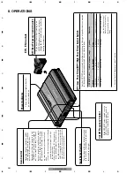
Page 24: ...LPF HPF select switch is set to LPF or HPF you can select a cut off frequency from 40 to 120 Hz Power Indicator The power indicator lights when the power is switched on LPF Low Pass Filter HPF High Pass Filter Select Switch Set the LPF HPF select switch as follows according to the type of speaker that is connected to the speaker output connector and the car stereo system LPF HPF Select Audio frequ...

Reviews: