background image

ORDER NO.

PIONEER CORPORATION


28-8, Honkomagome 2-chome, Bunkyo-ku, Tokyo 113-0021, Japan

PIONEER ELECTRONICS (USA) INC.

  P.O. Box 1760, Long Beach, CA 90801-1760, U.S.A.

PIONEER EUROPE NV

  Haven 1087, Keetberglaan 1, 9120 Melsele, Belgium

PIONEER ELECTRONICS ASIACENTRE PTE. LTD.

  2 Jalan Kilang Barat, #07-01, Singapore 159346

    PIONEER CORPORATION 2019

GM-D9705/XEVEL

CRT6391

CLASS D FIVE-CHANNEL AMPLIFIER

GM-D9705

/XEVEL

GM-DX975

/XEVEL

K-ZZZ JAN. 2019

Summary of Contents for GM-D9705/XEVEL

Page 1: ...P O Box 1760 Long Beach CA 90801 1760 U S A PIONEER EUROPE NV Haven 1087 Keetberglaan 1 9120 Melsele Belgium PIONEER ELECTRONICS ASIACENTRE PTE LTD 2 Jalan Kilang Barat 07 01 Singapore 159346 PIONEER CORPORATION 2019 GM D9705 XEVEL CRT6391 CLASS D FIVE CHANNEL AMPLIFIER GM D9705 XEVEL GM DX975 XEVEL K ZZZ JAN 2019 ...

Page 2: ... for example in circuit diagrams or lists of components a symbol is used to indicate that a specific component shall be replaced only by the component specified in that documentation for safety reasons the following symbol shall be used CAUTION This service manual is intended for qualified service technicians it is not meant for the casual do it yourselfer Qualified technicians have the necessary ...

Page 3: ...nectors during power on mode may damage the ICs inside the unit Please be sure to conduct line process to original status if you make assembling after repair Please be careful of not to apply static charge onto integrated circuits etc when you conduct repair work Especially please use soldering iron with its tip grounded Also please use a pair of tweezers with static charge protection capability i...

Page 4: ...ust the height of the replaced parts to match the board and fix it with solder Apply silicon grease GEM1057 to the backside of it Notes on soldering For environmental protection lead free solder is used on the printed circuit boards mounted in this unit Be sure to use lead free solder and a soldering iron that can meet specifications for use with lead free solders for repairs accompanied by rework...

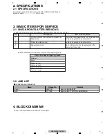
Page 5: ... reappeared Audio and operations must be normal Confirm whether the customer complaint has been solved Item to be checked regarding audio Distortion Noise Volume too low Volume too high Volume fluctuating Sound interrupted 2 Audio and operations must be normal Check the output sound 3 No scratches or dirt on its appearance after receiving it for service Appearance check See the table below for the...

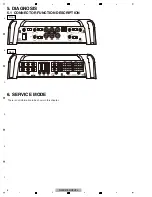
Page 6: ...6 GM D9705 XEVEL 1 2 3 4 A B C D E F 1 2 3 4 5 DIAGNOSIS 5 1 CONNECTOR FUNCTION DESCRIPTION 6 SERVICE MODE Front Rear There is not information to be shown in this chapter ...

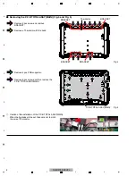
Page 7: ... Fig 1 Note While the photograph shown is slightly different from this model in shape the disassembly procedure is the same Removing the Chassis Fig 1 1 2 Remove 4 pcs screw Pull and remove the P C B TOTAL ASSY SW IN Fig 2 Fig 3 1 1 1 Removing the P C B TOTAL ASSY SW IN Fig 2 and Fig 3 1 2 Chassis P C B TOTAL ASSY SW IN ...

Page 8: ...e 8 pcs screw and then remove the P C B TOTAL ASSY MAIN Fig 4 Fig 5 3 1 1 1 1 1 1 3 3 4 4 4 4 4 4 4 4 Removing the P C B TOTAL ASSY MAIN Fig 4 and Fig 5 3 1 1 1 BRACKET BRACKET _ Caution of Re installation of the P C B TOTAL ASSY MAIN When the heatsink will be set take care not to pinch the wire of Thermistor P C B TOTAL ASSY MAIN BRACKET BRACKET Thermistor ...

Page 9: ...9 GM D9705 XEVEL 5 6 7 8 5 6 7 8 A B C D E F 8 EACH SETTING AND ADJUSTMENT GYL1006 Bonding Position There is not information to be shown in this chapter ...

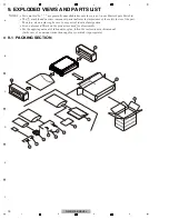
Page 10: ...found on some component parts indicates the importance of the safety factor of the part Therefore when replacing be sure to use parts of identical designation Screw adjacent to mark on the product are used for disassembly For the applying amount of lubricants or glue follow the instructions in this manual In the case of no amount instructions apply as you think it appropriate 1 2 3 4 5 6 9 7 10 11...

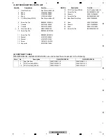
Page 11: ...ench S 3 mm 1580210036000V 5 Hexagonal Wrench S 1 5 mm 1580210016000V 6 Cable Assy L308121040010S 7 Screw Tapping 3 mm x 10 mm B010430103B10V 8 Bass Boost Remote Control 7025CX1801100 9 Screw Tapping 4 mm x 18 mm B010440183B10V 10 Cushion snow 6230214784000V 11 Box Gift See Contrast table 2 12 Box Outer Carton See Contrast table 2 Mark No Description Part No Mark No Description GM D9705 XEVEL GM D...

Page 12: ...12 GM D9705 XEVEL 1 2 3 4 A B C D E F 1 2 3 4 9 2 EXTERIOR SECTION 1 2 3 5 10 12 13 14 13 13 14 14 14 16 17 18 10 6 6 8 6 4 7 9 10 10 11 10 15 15 17 19 19 19 14 A B 21 22 20 23 24 ...

Page 13: ...ew Tap Tite B020030081W10SV 11 Screw Tap Tite B020030081B10SV 12 Bracket 4010216766000V 13 Bracket 4010216766100V 14 Screw 1507041146010SV 15 Supporter 4070212667000V 16 P C B Total Assy SW IN See Contrast table 2 17 Screw Tap Tite B020930061B10SV 18 Chassis 3200215766000V 19 Screw Tap Tite B020030103B10SV 20 Bass Boost Total Assy 3208215826000 21 Case 3030212091000V 22 Chassis 3207215826000V 23 K...

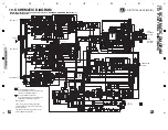
Page 14: ... C76 NM 1608 C77 NM 1608 R71 22 1W RADIAL 3 2 1 D28 MBRF20200CTR 1 2 3 D29 MBRF20200CT C78 1N 250V 2012 C82 1N 250V 2012 R54 22 1W RADIAL R197 22 1W RADIAL L6 0 2012 TH1 PRF18BB471QB5RB Q86 KRA105S D80 LBAS16HT1G Q87 KRA105S R208 4K7 Q34 MMBT5551 R3 8K2 TH2 DHPTHF1608471P95T D15 LBAS16HT1G R82 4K7 Q36 MMBT5551 R86 8K2 TH3 NTC 5K D16 LBAS16HT1G R89 470 Q39 MMBT5551 R157 8K2 R4 11K R67 16K R87 8K2 R...

Page 15: ...27N M 100V 1 2 3 4 5 6 7 8 9 10 11 CN55 C22541 2585 11G R267 10K C518 100 16V R268 180K R269 4K7 C512 68N M 100V 1 2 3 VR5 A C50K 4 R270 470 C175 180N M 100V 4 5 6 VR5 B C50K 4 R271 10K R272 22K 4 3 2 1 CN1 B551N 44GF M009 1 2 3 4 5 6 8 7 9 10 11 12 13 14 IC55 NJM2172V OPinA OPinA OPoutA EVRouA VcntA VcntB V inB inB outB EoutB REFin Vref GND CM2 CM1 1 2 3 4 5 6 7 8 IC15 NJM4580CG CM2 CM1 1 2 3 4 5...

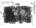
Page 16: ... further information for respective destinations be sure to check with the schematic dia gram 2 Viewpoint of PCB diagrams SIDE A 11 PCB CONNECTION DIAGRAM A P C B TOTAL ASSY MAIN A A CH B SPEAKER OUTPUT POWER GND S CONTROL CH B SPEAKER OUTPUT SUBWOOFER OUTPUT SUBWOOFER OUTPUT CH A SPEAKER OUTPUT CH A SPEAKER OUTPUT FUSE2 30A FUSE2 30A FUSE2 30A FRONT A_FREQ B_FREQ LPF HPF A_GAIN 2CH 4CH INPUT LPF ...

Page 17: ...17 GM D9705 XEVEL 5 6 7 8 5 6 7 8 A B C D E F A P C B TOTAL ASSY MAIN A A SIDE B ...

Page 18: ... B C D E F 1 2 3 4 11 2 P C B TOTAL ASSY SW IN B P C B TOTAL ASSY SW IN SIDE A B B SIDE B B P C B TOTAL ASSY SW IN A CN2 CN51 VR3 B FREQ SLOPE GAIN A B SW INPUT POWER PROTECT INDICATOR BASS BOOST REMOTE BASS BOOST REMOTE CONTROL ...

Page 19: ...NEAR OP J121458000050S IC 24 IC LINEAR OP J121458000050S IC 25 IC LINEAR OP J121458000050S IC 51 IC LINEAR OP J121458000050S IC 58 IC ANALOG J080209201010S IC 502 IC LINEAR OP J121458000050S IC 516 IC ANALOG J080209301010S Q 1 SEMI CHIP TR NPN 2SC J522555100010S Q 2 SEMI CHIP TR NPN 2SC J522555100010S Q 3 SEMI CHIP TR NPN 2SC J522437900010S Q 4 SEMI CHIP TR PNP 2SA J520015040150S Q 5 SEMI CHIP TR ...

Page 20: ...WITCHING CHIP K005041480230S D 23 D SWITCHING CHIP K005041480230S D 24 D SCHOTTKY K120020200050S D 25 D SCHOTTKY K120020200040S Circuit Symbol and No Part No D 26 D SWITCHING CHIP K005041480230S D 27 D SWITCHING CHIP K005041480230S D 28 D SCHOTTKY K120020200050S D 29 D SCHOTTKY K120020200040S D 30 D SWITCHING CHIP K005041480230S D 31 D SWITCHING CHIP K005041480230S D 32 D SWITCHING CHIP K005041480...

Page 21: ...6267000S R 46 C120056267000S R 49 N113138622020S R 54 N113138622010S R 60 N113038610210S R 63 N113038610210S R 70 N113138622010S R 71 N113138622010S R 174 N113136665210S R 197 N113138622010S R 222 C1202R2069000S R 224 N113138647210S R 586 N113138610020S R 587 N113138610020S R 655 N113138647030S R 656 N113138647030S R 657 N113138647030S R 658 N113138647030S Circuit Symbol and No Part No R 730 N1131...

Page 22: ...0S IC 20 IC LINEAR OP J121458000050S IC 55 IC LINEAR OP J121217201010S LED1 LED ROUND K500032601140S SW3 SW SLIDE SLOPE G060221900020S SW4 SW SLIDE A B SW INPUT G060221900020S VR5 VR ROTARY 50 kohm FREQ C450105300040S VR7 VR ROTARY 10 kohm GAIN C450101300050S CN1 JACK MODULAR G4060RJ220010S CN55 CN WAFER 2 5 MM L102225422290S CAPACITORS C 18 D041100087230S C 22 D041100087230S C 164 D041220087230S ...

Reviews: