background image

Summary of Contents for GM-D9705

Page 1: ...Pioneer Owner s Manual Mode d emploi CLASS D FIVE CHANNEL AMPLIFIER AMPLIFICATEUR ACINQ CANAUX DE CLASSED GM D9705 GM DX975 English Franrais ...

Page 2: ...t without appropriate authorization may invalidate the user s right to operate the equipment En Visit our website Visit us at the following site http pioneer jp en info globalnetwork We offer the latest information about PIONEER CORPORATION on our website The Safety of Your Ears is in Your Hands Get the most out of your equipment by playing it at a safe level a level that lets the sound come throu...

Page 3: ...of the separately sold battery wire or the amplifier fuse blows Deter mine and resolve the cause then replace the fuse with and identical equivalent En Always install the amplifier on a flat surface Do not install the amplifier on a surface that is not flat or on a surface with a protrusion Doing so could result in malfunction When installing the amplifier do not allow parts such as extra screws t...

Page 4: ...gets high If the temperature gets too high the POWER PROTECT indicator will turn off and the amplifier wi1 1shut down En _s_e_tt_in_g_t_h_e_u_n_it ____ Component names and functions Rear side To adjust the switch use a flathead screwdri ver if needed CD FREQ cut off frequency control Cut off frequency selectable from 40 Hz to 500 Hz Set the LPF HPF select switch to LPF or HPF according to the type...

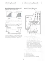
Page 5: ...F from 12 dB shallow slope or 24 dB sharp slope BB REMOTE bass boost level remote control jack By connecting the Bass boost level remote control to the jack on the main unit you will En be able to select a bass boost level from OdB to 18dB The bass boost level setting applies only to the subwoofer output For instruction of connecting the bass boost remote control to the amplifier see the Connectio...

Page 6: ...ut even if the amplifier gain is raised the output power wi11 change only slightly En Conneding the units Connection diagram CD V CD Battery wire sold separately The maximum length of the wire be tween the fuse and the positive 8 term inal of the battery is 30cm 12 in Forthe wire size refer to Connecting the power terminal The battery wire the ground wire and the optional direct ground wire must b...

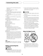
Page 7: ...st be set For details refer to Connecting the car stereo Before connecting the amplifier AwARNING Secure the wiring with cable clamps or adhe sive tape To protect the wiring wrap sections in contact with metal parts in adhesive tape En Never cut the insulation of the power supply to feed power to other equipment Current ca pacity of the wire is limited AcAUTION Never wire the speaker negative cabl...

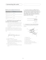
Page 8: ...positive battery term inal CD CD Positive terminal Battery wire sold separately The maximum length of the wire between the fuse and the positive terminal of the battery is 30 cm 12 in Fuse 100 A sold separately Each amplifier must be separately fused at 100A En 2 Use wire cutters or a utility knife to strip the end of the battery wire ground wire and system remote control wire to ex pose about 10 ...

Page 9: ...er or passengers if the vehicle stops suddenly Places where it may interfere with the dri ver such as on the floor in front of the dri ver s seat Install tapping screws in such a way that the screw tip does not touch any wire This is im portant to prevent wires from being cut by vi bration of the car which can result in fire Make sure that wires do not get caught in the sliding mechanism of the se...

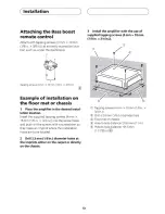
Page 10: ...suppl ied tapping screws 4 mm x 18 mm 1 8 in x 3 4 in into the screw holes and push on the screws with a screwdriver so they make an imprint where the installation holes are to be located 2 Drill 2 5 mm 1 8in diameter holes at the imprints either on the carpet or directly on the chassis En 3 Install the amplifier with the use of supplied tapping screws 4mm x 18mm 1 8 in x 3 4 in CD Tapping screws ...

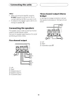
Page 11: ...he speakers Connecting the speakers The speaker output mode can be five channel output or three channel output Connect the speaker leads based on the mode and the figure shown below Five channel output CD Left Right Speaker output A G Speaker output B Subwoofer output En Three channel output Stereo bridge In the case of a bridge connection connect the speaker leads based on the figure shown below ...

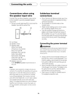
Page 12: ...ct the head unit and al l amplifiers via the system remote control wire En Solderless terminal connections Since the wire will become loose over time it must be periodically inspected and tigh tened as necessary Do not solder or bind the ends of the twisted wires Fasten while making sure to not to clamp the insulating sheath of the wire Use the supplied hexagonal wrench to tighten and loosen the t...

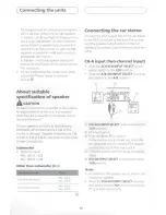
Page 13: ...d other bridge connections Subwoofer Nominal input Min 350W 4 Q Min 600W 2 Q Other than subwoofer 4 n Four channel output Max input Min 150W Two channel output Max input Min 400W En ______ Connecting the car stereo Connect the RCA output jack of the car stereo to the RCA input jack of the amplifier or con nect the speaker output wire from the car stereo to the speaker input terminal of the am plif...

Page 14: ...e speaker output refer to Con necting the speakers CH A CH SW input Slide the 2CH 4CH INPUT SELECT input select switch to the 2CH position Slide the A 8 SW INPUT SELECT input se lect switch to the SW position En Notes For details on the speaker output refer to Con necting the speakers When the 2CH 4CH INPUT SELECT input se lect switch is set to 2CH do not connect any thing to RCA input jack B CH A...

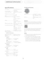
Page 15: ...dB oct High pass filter A B CH Cut off frequency 40 Hz to 500 Hz Cut off slope 12 dB oct Bass boost SW Frequency 50 Hz Level 0 dB to 18 dB Gain control RCA 200 mV to 6 5 V Speaker 0 8 Vto 16 V Maximum input level impedance RCA 6 5 V 25 kn Speaker 16 V 12 kn En C _ ___ CEA2006 Specifications f l CEA 266 Power output 75W RMS x 4 350W x 1 RMS 4n and 1 THD N S N ratio 75 dBA reference 1W into 4n GM DX...

Page 16: ...erhongkong com hk http www pioneer twn com tw http www pioneer latin com Haven 1087 Keetberglaan 1 B 9120 Melsele Belgium Belgique TEL 0 3 570 05 11 PIONEER ELECTRONICS ASIACENTRE PTE LTD 2 Jalan Kilang Barat 07 01 Singapore 159346 TEL 65 6378 7888 PIONEER ELECTRONICS AUSTRALIA PTY LTD 5 Arco Lane Heatherton Victoria 3202 Australia TEL 03 9586 6300 PIONEER ELECTRONICS DE MEXICO S A DE C V Blvd Man...

Reviews: