En(6/9)
Connecting the units
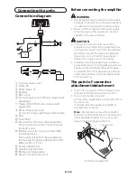
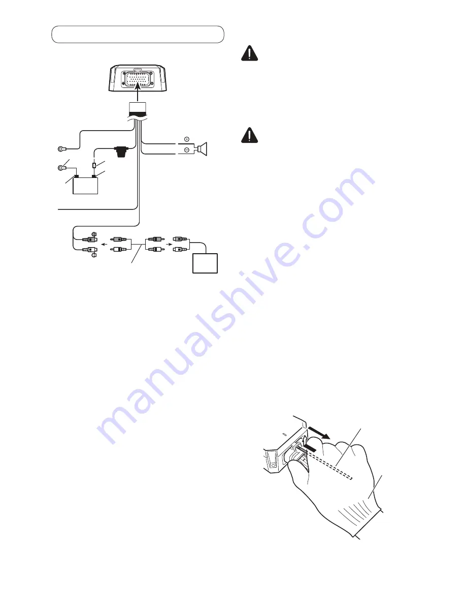
Connection diagram
1
3
2
4
8
9
a
g
5
6
7
f
b
d
c
e
1
To power cable input
2
White:
3
White/black:
4
Speaker
5
RCA input
6
Connecting wire with RCA pin plugs (sold
separately)
7
Headunit with RCA output jacks (sold
separately)
8
Black (chassis ground)
Connect to a clean, paint-free metal location.
9
Red
a
Fuse (30 A)
b
Ground wire, Terminal (sold separately)
The ground wires must be the same size as
the battery wire.
c
Battery wire with Fuse [more than 30A]
(sold separately)
The maximum length of the wire between
the fuse and the positive
terminal of the
battery is 30 cm (12 in.).
d
Positive
terminal
e
Negative (
) terminal
f
Battery (sold separately)
g
System remote control wire
!DENQDÐBNMMDBSHMFÐSGDÐ@LOKHÆDQ
WARNING
Secure the wiring with cable clamps or adhe-
sive tape. To protect the wiring, wrap sections
in contact with metal parts in adhesive tape.
Never cut the insulation of the power supply
to feed power to other equipment. Current
capacity of the wire is limited.
CAUTION
If the system remote control wire of the
amplifier is connected to the power terminal
via the ignition switch (12 V DC), the amplifier
will remain on with the ignition whether the
headunit is on or off, which may exhaust
battery if the engine is at rest or idling.
Install and route the separately sold marine
grade battery wire, marine grade ground wire,
speaker wires and the amplifier as far away
as possible from the radio antenna, antenna
cable, tuner and any communications equip-
ment and wiring.
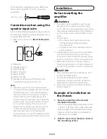
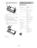
The point of connector
attachment/detachment
Push in the connector until a clicking sound
is heard, confirming a secure connection.
How to remove the connector:
(1) Insert the supplied tool into the lock part of
the connector.
(2) Gently raise the release locking tab to
separate the connector.
Note
:
Attempting to remove the connector
by force or pulling from the wire harness can
cause damage. To avoid injury, use a work
glove to help with gripping the tool.
2
1
Supplied tool
Work glove
- Continue to page 7/9 -

