background image

En(3/10)

About the protection function

This product has a protection function. If this 
product detects something abnormal, the Power/
Protect indicator will turn red and the operation 
of amplifier will be stopped.
Possible causes include:

  When the temperature inside the product 

becomes high

  When speaker output detects an abnormality

  When the supply voltage is out of 

specification

 Important (Serial number)

The serial number is located on the bottom of 
this unit. Be sure to record this number on the 
enclosed warranty card before installation.

  Do not attempt to disassemble or modify 

this unit. Doing so may result in fire, electric 
shock or other malfunction. Damage or 
defects resulting from alterations or modifica-
tions not authorized in writing by Pioneer are 
excluded from limited warranty coverage.

  Do not install the amplifier in a location 

exposed to direct sunlight or excessive heat, 
humidity or dust.

  While this amplifier is designed to be water-re-

sistant, it should never be submerged under 
water or subjected to high-pressure water 
spray.

  Install the amplifier in a dry and well-ventilated 

environment, where other equipment will not 
interfere with it.

  When drilling holes in the chassis for instal-

lation, take precautions so as not to contact, 
damage or obstruct pipes, fuel lines, tanks or 
electrical wiring. Failure to take such precau-
tions may result in fire.

  To ensure proper heat dissipation of the 

amplifier, ensure the following during 
installation:

  Allow adequate space above the amplifier 

for proper ventilation.

  Do not mount the amplifier in the engine 

compartment or in any areas of extreme 
heat.

  Do not cover the amplifier.


Ask your dealer or installation profes-
sional to install/uninstall this prod-

TBSÐ(MBNQQDBSÐHMRS@KK@SHNMÐB@MÐBQD@SDÐ

dangerous hazards or interfere with 

AN@SÐNODQ@SHNM

  Keep small items such as bolts, screws and 

tools out of the reach of children. Swallowing 
can cause serious injury. If swallowed, con-
sult a doctor immediately.

 CAUTION

  Always keep the volume low enough to hear 

outside sounds.

  Extended use of the amplifier while the 

engine is at rest or idling may exhaust the 
battery.

  The graphical symbol 

 placed on the 

product means this is an electronic product 
requiring direct current electrical power.

Summary of Contents for GM-ME300X4C

Page 1: ...Owner s Manual Mode d emploi Manual de instrucciones MARINE 4 CHANNEL AMPLIFIER AMPLIFICATEUR 4 CANAUX MARIN AMPLIFICADOR MARINO DE 4 CANALES GM ME300X4C English Français Español ...

Page 2: ...e the receiving antenna Increase the separation between the equipment and receiver Connect the equipment into an out let on a circuit different from that to which the receiver is connected Consult the dealer or an experienced radio TV technician for help FEDERAL COMMUNICATIONS COMMISSION SUPPLIER S DECLARATION OF CONFORMITY Product Name Marine 4 channel Amplifier Model Number GM ME300X4C Responsib...

Page 3: ...t has been properly terminated for marine use to make a direct connection to the negative bus bar or negative ground distribution system Do not attempt to ground the amplifier using the mounting screws Use fused marine grade battery wire sold separately of adequate gauge that has been properly terminated for marine use to make a direct connection to the positive bus bar or positive distribution sy...

Page 4: ...high pressure water spray Install the amplifier in a dry and well ventilated environment where other equipment will not interfere with it When drilling holes in the chassis for instal lation take precautions so as not to contact damage or obstruct pipes fuel lines tanks or electrical wiring Failure to take such precau tions may result in fire To ensure proper heat dissipation of the amplifier ensu...

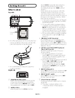
Page 5: ...to the NOR normal position For use with an RCA equipped Pioneer headunit with maximum output of 4 V or more adjust level to match that of the stereo output For use with an RCA equipped headunit with output of 4 V set to the H High position 3 FREQ Hz cutoff frequency The cutoff frequency is selectable from 50 Hz to 500 Hz when the LPF HPF select switch is set to either LPF or HPF For more informati...

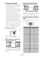
Page 6: ...orrect volume and gain set tings the unit sound may cut out period ically In such cases please contact an authorized Pioneer Service Company Gain volume of this unit 0 5 V Maximum preout level 2 V Maximum preout level 4V Above illustration shows NOR normal gain setting 1DK SHNMRGHOÐADSVDDMÐ LOKHÆDQÐF HMÐ and headunit output power If amplifier gain is raised improperly this will simply increase dis...

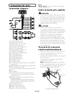
Page 7: ...ING Secure the wiring with cable clamps or adhe sive tape To protect the wiring wrap sections in contact with metal parts in adhesive tape Never cut the insulation of the power supply to feed power to other equipment Current capacity of the wire is limited CAUTION If the system remote control wire of the amplifier is connected to the power terminal via the ignition switch 12 V DC the amplifier wil...

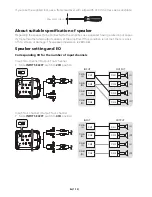
Page 8: ...e amplifier If this condition is not met there is a risk RI ILUH VPRNH RU GDPDJH 7KH VSHDNHU LPSHGDQFH LV WR Speaker setting and I O Corresponding I O for the number of input channels Input Two channel Output Four channel Slide INPUT SELECT switch to 2CH position CH A CH A CH B CH B CH1 CH1 CH2 CH3 CH4 CH2 CH3 CH4 INPUT OUTPUT L L L L R R R R Input Four channel Output Four channel Slide INPUT SELE...

Page 9: ...to switch the INPUT SENS switch to SP speaker 1 Headunit 2 Speaker output 3 Red Right 4 Black Right 5 Black Left 6 White Left 7 Speaker input wire with RCA pin cord to the RCA input jack of this unit Note If speaker input wires from a headunit are connected to this amplifier the amplifier will automatically turn on when the headunit is turned on When the headunit is turned off the amplifier turns ...

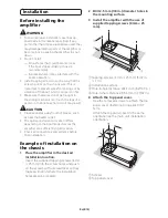
Page 10: ... the heater outlet The optimal installation location differs depending on the boat model Secure the amplifier at a sufficiently rigid location Check all connections and systems before final installation Example of installation on the chassis Ä Ä K BDÄSGDÄ LOKH DQÄHMÄSGDÄCDRHQDCÄ installation location Insert the supplied tapping screws 4 mm 25 mm into the screw holes and push on the screws with a s...

Page 11: ...utoff slope 12 dB oct High pass filter Cutoff frequency 50 Hz to 500 Hz Cutoff slope 12 dB oct Gain volume RCA 0 2 V to 6 5 V Speaker 0 8 V to 16 V Maximum input level impedance RCA 6 5 V 25 k Speaker 16 V 12 k Waterproof JIS IEC protection class 7 IPX7 equivalent self certified Dustproof JIS IEC protection class 6 IP6X equivalent self certified 3 Ä2ODBH B SHNMR Power output 75 W RMS 4 Channels at...

Page 12: ...pioneerelectronics ca PIONEER CORPORATION 28 8 Honkomagome 2 chome Bunkyo ku Tokyo 113 0021 JAPAN PIONEER ELECTRONICS USA INC P O Box 1540 Long Beach California 90801 1540 U S A TEL 800 421 1404 A1 000030 9L A UC KNZZ20K 2020 PIONEER CORPORATION ...

Page 13: ...LL APPLY AFTER THE WARRANTY PERIOD Some states and provinces do not allow limitations on how long an implied warranty lasts so the above limitations or exclusions may not apply to you This warranty gives you specific legal rights and you may also have other rights which vary from state to state or province to province To the extent any provision of this limited warranty is deemed invalid or unenfo...

Page 14: ...utorisent pas les limitations sur la durée d une garantie implicite Par conséquent il se pourrait que certaines des limitations ou exclusions précitées ne s appliquent pas à vous Cette garantie vous confère des droits spécifiques légaux mais vous pouvez bénéficier d autres droits qui peuvent varier selon les États ou les provinces Dans la mesure où toute disposition de cette garantie limitée est c...

Reviews: