background image

15

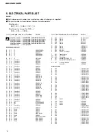
GM-X362,X262

R

260

RD1/4PU161J

R

261

RD1/4PU473J

R

262

RD1/4PU473J

R

263

RD1/4PU221J

R

264

RD1/4PU562J

R

265

RD1/4PU222J

R

266

RD1/4PU473J

R

267

RD1/4PU473J

R

268

0.22

HZC0003

R

269

0.22

HZC0003

R

270

0.22

HZC0003

R

271

0.22

HZC0003

R

272

RD1/2PM100J

R

601

RD1/4PU393J

R

602

RD1/4PU393J

R

605

RD1/4PU564J

R

606

RD1/4PU564J

R

609

RD1/2PM473J

R

610

RD1/2PM473J

R

613

RS1/10S472J

R

614

RS1/10S472J

R

651

RS1/10S104J

R

652

RS1/10S103J

R

653

RS1/10S472J

R

654

RD1/4PU392J

R

655

RS1/10S472J

R

656

RS1/10S222J

R

657

RS1/10S221J

R

658

RS1/10S102J

R

659

RS1/10S473J

R

660

RS1/10S103J

R

661

RS1/10S103J

R

662

RS1/10S222J

R

663

RS1/10S472J

R

664

RS1/10S392J

R

665

RS1/10S392J

R

666

RS1/10S103J

R

667

RS1/10S472J

R

668

RS1/10S473J

R

669

RS1/10S223J

R

670

RS1/10S223J

R

671

RS1/10S223J

R

672

RS1/10S472J

R

673

RD1/4PU101J

R

674

RD1/4PU221J

R

675

RD1/4PU152J

R

676

RD1/2PM681J

R

801

RS1/10S471J

R

802

RS1/10S471J

R

803

RS1/10S223J

R

804

RS1/10S223J

R

805

RN1/10SE2201D

R

806

RN1/10SE2201D

R

807

RN1/10SE2201D

R

808

RN1/10SE2201D

R

809

RS1/10S104J

R

810

RS1/10S104J

R

811

RN1/10SE2201D

R

812

RN1/10SE2201D

R

813

RN1/10SE2201D

R

814

RN1/10SE2201D

R

831

RS1/10S683J

R

832

RS1/10S683J

R

953

RD1/4PU392J

R

954

RD1/4PU101J

R

955

RS1/10S473J

R

956

RS1/10S102J

R

957

RS1/10S153J

R

958

(EW,ES model)

RS1/10S105J

R

959

RD1/4PU101J

R

960

RD1/4PU332J

R

961

RD1/4PU101J

R

962

RS1/10S332J

R

963

RS1/10S472J

R

964

RS1/10S472J

R

965

RS1/10S472J

R

966

RD1/4PU272J

R

967

RD1/4PU272J

R

972

RD1/2PM121J

R

973

RD1/2PM121J

R

976

RD1/2PM220J

R

977

RD1/2PM220J

R

978

RD1/2PM220J

R

979

RD1/2PM220J

R

980

RD1/4PU100J

R

981

RD1/4PU100J

R

982

RD1/4PU472J

R

983

RD1/4PU472J

R

984

RD1/4PU563J

R

985

RD1/4PU104J

R

986

RD1/4PU183J

CAPACITORS

C

102

CKSQYB274K16

C

103

CKSQYB154K16

C

151

CEAS101M10

C

152

CCSQSL680J50

C

153

CFTNA224J50

C

154

CFTNA224J50

C

155

CCSQCH220J50

C

156

CCCCH330J100

C

157

CCCCH330J100

C

158

CCSQCH220J50

C

159

CFTLA223J50

C

160

CFTLA333J50

C

171

CCSQCH101J50

C

172

CCSQCH101J50

C

202

CKSQYB274K16

C

203

CKSQYB154K16

C

251

CEAS101M10

C

252

CCSQSL680J50

C

253

CFTNA224J50

C

254

CFTNA224J50

C

255

CCSQCH220J50

C

256

CCCCH330J100

C

257

CCCCH330J100

C

258

CCSQCH220J50

C

259

CFTLA223J50

C

260

CFTLA333J50

C

271

CCSQCH101J50

C

272

CCSQCH101J50

C

651

220µF/10V

HZC0001

C

652

CKSQYB103K50

C

653

CKSQYB103K50

C

654

CKSQYB103K50

C

655

CEAS100M16

C

656

CEAS100M16

C

657

CEAS470M16

C

659

CKSQYB103K50

C

660

CEAS220M16

C

661

470µF/16V

HZC0002

C

662

CKSQYB103K50

C

663

CQMA103J50

=====Circuit Symbol and No.===Part Name

Part No.

---

------

------------------------------------------

-------------------------

=====Circuit Symbol and No.===Part Name

Part No.

---

------

------------------------------------------

-------------------------

Summary of Contents for GM-X262

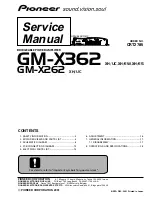
Page 1: ...pore 159936 C PIONEER CORPORATION 2001 K ZZD DEC 2001 Printed in Japan ORDER NO CRT2785 BRIDGEABLE POWER AMPLIFIER GM X362 XH UC XH EW XH ES Service Manual GM X362 XH UC CONTENTS 1 SAFETY INFORMATION 2 2 EXPLODED VIEWS AND PARTS LIST 4 3 SCHEMATIC DIAGRAM 8 4 PCB CONNECTION DIAGRAM 10 5 ELECTRICAL PARTS LIST 14 6 ADJUSTMENT 16 7 GENERAL INFORMATION 17 7 1 DISASSEMBLY 17 8 OPERATIONS AND SPECIFICAT...

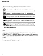
Page 2: ... protect the product from damages or failures that may be caused during transit the shipping mode should be set or the shipping screws should be installed before shipping out in accordance with this manual if necessary 1 Product safety You should conform to the regulations governing the product safety radio and noise and other regulations and should keep the safety during servicing by following th...

Page 3: ...3 GM X362 X262 ...

Page 4: ...4 GM X362 X262 2 EXPLODED VIEWS AND PARTS LIST 2 1 PACKING ...

Page 5: ...art No 1 PACKING SECTION PARTS LIST NOTE Parts marked by are generally unavailable because they are not in our Master Spare Parts List Screws adjacent to mark on the product are used for disassembly For the applying amount of lubricants or glue follow the instructions in this manual In the case of no amount instructions apply as you think it appropriate Part No Mark No Description GM X362 XH UC GM...

Page 6: ...6 GM X362 X262 2 2 EXTERIOR A ...

Page 7: ...ack CN801 HZK0002 20 Terminal CN901 HZK0003 21 Terminal CN905 HZK0004 22 Terminal CN906 HZK0004 23 Connector CN904 HZK0005 24 Holder HZN0009 25 26 Lighting Conductor Unit HZX0001 27 Screw PPZ30P120FZK 28 Sheet HZN0016 29 Spacer HZN0017 30 Screw PBA30P120FMC 31 Washer WH30FZN 32 Screw PPZ30P100FZK 33 Screw BBZ30P100FMC Part No Mark No Description GM X362 XH UC GM X262 XH UC GM X362 XH EW GM X362 XH...

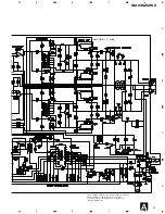
Page 8: ...2 0 022 R022 Symbol indicates a resistor No differentiation is made between chip resistors and discrete resistors NOTE Symbol indicates a capacitor No differentiation is made between chip capacitors and discrete capacitors A 8 GM X362 X262 A 1 2 3 4 B C D 1 2 3 4 3 SCHEMATIC DIAGRAM 3 1 AMP UNIT Note When ordering service parts be sure to refer to EXPLODED VIEWS AND PARTS LIST or ELECTRICAL PARTS ...

Page 9: ... ES model HZS0003 HZE0005 The mark found on some component parts indicates the importance of the safety factor of the part Therefore when replacing be sure to use parts of identical designation 9 GM X362 X262 5 6 7 8 A B C D 5 6 7 8 A ...

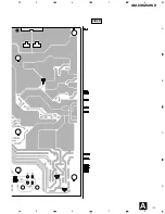
Page 10: ...PCB DIAGRAMS 1 The parts mounted on this PCB include all necessary parts for several destination For further information for respective destinations be sure to check with the schematic diagram 2 Viewpoint of PCB diagrams Capacitor Connector P C Board Chip Part SIDE A SIDE B A FUSE SPEAKER INPUT A ...

Page 11: ...11 GM X362 X262 5 6 7 8 A B C D 5 6 7 8 SPEAKER OUTPUT BFC LPF GAIN INPUT L R SIDE A A ...

Page 12: ...12 GM X362 X262 A 1 2 3 4 B C D 1 2 3 4 A AMP UNIT A ...

Page 13: ...13 GM X362 X262 5 6 7 8 A B C D 5 6 7 8 SIDE B A ...

Page 14: ...dicate chip components Chip Resistor RS1 _S___J RS1 __S___J Chip Capacitor except for CQS CKS CCS CSZS Unit Number HZW0001 GM X362 XH UC Unit Number HZW0002 GM X362 XH EW Unit Number HZW0003 GM X362 XH ES Unit Number HZW0004 GM X262 XH UC Unit Name Amp Unit MISCELLANEOUS IC 101 IC NJM4558MD IC 151 IC NJM2068M IC 651 IC PA2027A IC 801 IC NJM2068M IC 802 IC NJM2068M IC 951 IC UPC494C Q 151 Transisto...

Page 15: ...S1 10S683J R 953 RD1 4PU392J R 954 RD1 4PU101J R 955 RS1 10S473J R 956 RS1 10S102J R 957 RS1 10S153J R 958 EW ES model RS1 10S105J R 959 RD1 4PU101J R 960 RD1 4PU332J R 961 RD1 4PU101J R 962 RS1 10S332J R 963 RS1 10S472J R 964 RS1 10S472J R 965 RS1 10S472J R 966 RD1 4PU272J R 967 RD1 4PU272J R 972 RD1 2PM121J R 973 RD1 2PM121J R 976 RD1 2PM220J R 977 RD1 2PM220J R 978 RD1 2PM220J R 979 RD1 2PM220J...

Page 16: ... 952 CEAS221M10 C 953 CQMA102J50 C 954 CEAS2R2M50 C 955 CEAS100M16 C 956 3300µF 16V HZC0008 C 958 CQMA472J50 C 959 CQMA472J50 C 960 CQMA102J50 C 961 CQMA102J50 C 962 2200µF 35V HZC0007 C 963 2200µF 35V HZC0007 C 968 CEAS101M35 C 969 CEAS101M35 C 970 CEAS100M50 C 971 CEAS100M50 C 972 CKSQYB473K50 C 973 CKSQYB473K50 C 974 CEAS470M16 C 975 CEAS470M16 C 976 CFTNA564J50 Circuit Symbol and No Part Name ...

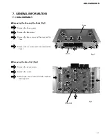
Page 17: ...anel Fig 1 Remove the three screws Remove the two screws Remove the two screws and then remove the Case Remove the six screws and then remove the Panel Fig 2 Panel Removing the Amp Unit Fig 2 Remove the eleven screws Remove the screw Remove the nine screws and then remove the Amp Unit Amp Unit ...

Page 18: ...18 GM X362 X262 8 OPERATIONS AND SPECIFICATIONS 8 1 OPERATIONS GM X362 XH EW ...

Page 19: ... on the front of the power amplifier clockwise If the sound distorts when the volume is turned up turn the gain control counter clockwise When using with an RCA equipped car stereo standard output of 500 mV set to the NORMAL position When using with an RCA equipped Pioneer car stereo with max output of 4 V or more adjust level to match the car stereo output level If you hear too much noise when us...

Page 20: ...s sold separately RCA input jack System remote control wire sold separately Connect the male terminal of this wire to the system remote control terminal of the car stereo SYSTEM REMOTE CONTROL The female terminal can be connected to the auto antenna relay control terminal If the car stereo does not have a system remote control terminal connect the male terminal to the power terminal through the ig...

Page 21: ...is unit when an audio signal is input Use this value when working out total current drawn by multiple power amplifiers GM X262 XH UC Power source 14 4 V DC 10 8 15 1 V allowable Grounding system Negative type Current consumption 11 3 A at continuous power 4 Ω Average current drawn 3 8 A 4 Ω for two channels 5 9 A 4 Ω for one channel Fuse 20 A Dimensions 279 W 61 H 157 D mm 11 W 2 3 8 H 6 1 8 D in ...

Page 22: ...arly the maximum current drawn by this unit when an audio signal is input Use this value when working out total current drawn by multiple power amplifiers GM X362 XH EW Power source 14 4 V DC 10 8 15 1 V allowable Grounding system Negative type Current consumption 11 3 A at continuous power 4 Ω Average current drawn 3 8 A 4 Ω for two channels 5 9 A 4 Ω for one channel Fuse 20 A Dimensions 279 W 61...

Reviews: