100
HTP-071
1
2
3
4
A
B
C
D
E
F
1
2
3
4
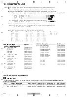
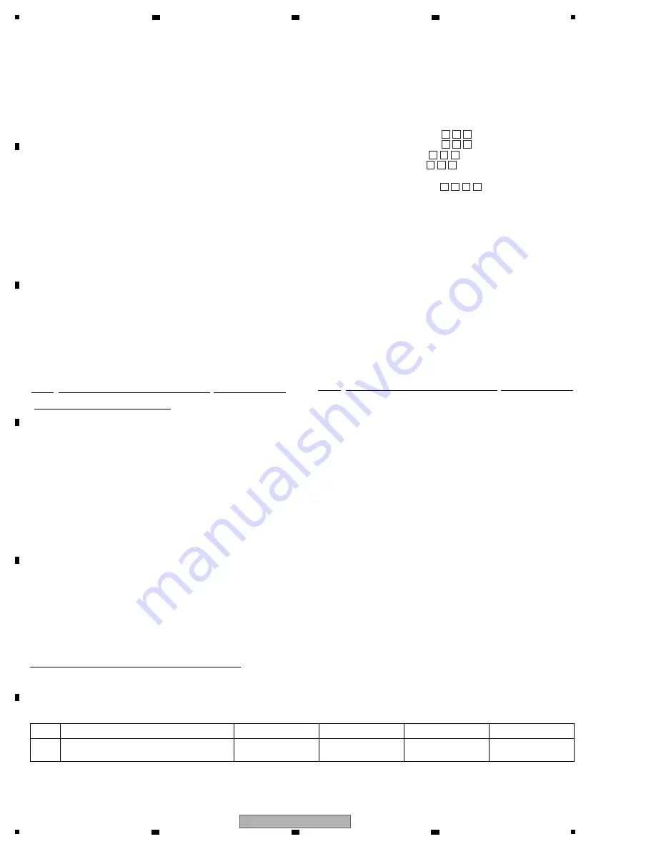
12. PCB PARTS LIST
CONTRAST OF PCB ASSEMBLIES
702
8
071121040-IL, 702
8
071121030-IL, 702
8
071121020-IL and 702
8
071121010-IL are constr
u
cted the same
except for the follo
w
ing:
-
Meaning of the figures and others in the parentheses in the parts list.
Example) IC 301 is on the point (face A, 91 of x-axis, and 111 of y-axis) of the corresponding PC board.
IC 301 (A, 91, 111) IC NJM2068V
5 6 2 1
1 R 0
R 5 0
5 6 1
4 7 3
NOTES:
-
Parts marked by “NSP” are generally unavailable because they are not in our Master Spare Parts List.
-
The
>
mark found on some component parts indicates the importance of the safety factor of the part.
Therefore, when replacing, be sure to use parts of identical designation.
-
When ordering resistors, first convert resistance values into code form as shown in the following examples.
Ex.1 When there are 2 effective digits (any digit apart from 0), such as 560 ohm and 47 k ohm (tolerance is shown by J = 5%,
and K = 10%).
560
Ω
→
56 × 10
1
→
561 ...................................................................RD1/4PU J
47
k
Ω
→
47 × 10
3
→
473 ...................................................................RD1/4PU J
0.5
Ω
→
R50 .................................................................................................RN2H K
1
Ω
→
1R0 .................................................................................................RS1P K
Ex.2 When there are 3 effective digits (such as in high precision metal film resistors).
5.62
k
Ω
→
562 × 10
1
→
5621 .................................................................RN1/4PC F
BKT
→
none
CLAMP
→
none
W
→
none
LUG
→
none
P
→
none
PACK
→
9***
CP
→
CN
CP
→
CN9***
FPC
→
CN9*** or CN
BEAD
→
L
F
→
FU
FLT
→
V
JACK
→
JA
JACK
→
JA9***
JK
→
JA
PT
→
T
REG
→
IC
REG
→
IC9***
RLY
→
RY
RMC
→
U
RES
→
X
XTAL
→
X9***
BD
→
L7***
LED
→
D8***
Z
→
D9***
ZD
→
D9***
DZ
→
D9***
SW
→
S
VEC
→
S9***
GND
→
KN
-
SCHEMATIC DIAGRAM and PCB CONNECTION DIAGRAM
→
-
PCB PARTS LIST
Mark No. Description Part No.
LIST OF ASSEMBLIES
N
S
P
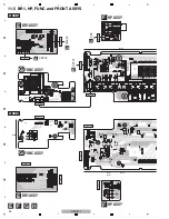
1..PCB TTL A
SS
Y FRONT
7025HK1103011-IL
2..FRONT A
SS
Y
7028071131010-IL
2..FUNCT A
SS
Y
7028071132010-IL
2..BR1 A
SS
Y
7028071133010-IL
2..HP A
SS
Y
7028071134010-IL
N
S
P
1..PCB TTL A
SS
Y D-MAIN
7025HK1103012-IL
2..D-MAIN A
SS
Y
7028071161010-IL
N
S
P
1..PCB TTL A
SS
Y INPUT
7025HK1103013-IL
2..DG A
SS
Y
7028071111010-IL
2..INPUT A
SS
Y
7028071112010-IL
N
S
P
1..PCB TTL A
SS
Y AMP
7025HK1103014-IL
2..AMP A
SS
Y
7028071141010-IL
N
S
P
1..PCB TTL A
SS
Y CNT
7025HK1103015-IL
2..CNT A
SS
Y
7028071151010-IL
N
S
P
1..PCB TTL A
SS
Y MAIN
7025HK1103040-IL
2..MAIN A
SS
Y (
S
YXE8)
7028071121040-IL
2..MAIN A
SS
Y (CXE)
7028071121030-IL
2..MAIN A
SS
Y (DLPWXE)
7028071121020-IL
2..MAIN A
SS
Y (AXE5)
7028071121010-IL
2..
S
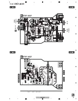
TBY A
SS
Y (
S
YXE8)
7028071122040-IL
2..
S
TBY A
SS
Y (CXE)
7028071122030-IL
2..
S
TBY A
SS
Y (DLPWXE)
7028071122020-IL
2..
S
TBY A
SS
Y (AXE5)
7028071122010-IL
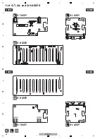
2..G-T A
SS
Y
7028071123010-IL
2..G-H A
SS
Y
7028071124010-IL
2..G-L A
SS
Y
7028071125010-IL
Mark No. Description Part No.
C
MAIN ASSY
Mark
Symbol and Description
702
8
071121040-IL
702
8
071121030-IL
702
8
071121020-IL
702
8
071121010-IL
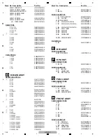
L1 COIL, FILTER-INDUCTOR
Not
u
sed
D330900001330-IL
D330900001330-IL
D330900001330-IL
601 TUNER, FM/AM
E9031041007
8
0-IL
E9030041007
8
0-IL
E9030041007
8
0-IL
E9030041007
8
0-IL
Summary of Contents for HTP-071
Page 9: ...9 HTP 071 5 6 7 8 5 6 7 8 A B C D E F ...
Page 12: ...12 HTP 071 1 2 3 4 A B C D E F 1 2 3 4 4 2 OVERALL BLOCK DIAGRAM H FRONT ASSY A INPUT ASSY ...
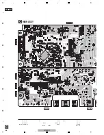
Page 89: ...89 HTP 071 5 6 7 8 5 6 7 8 A B C D E F C SIDE B CP1 CP3 CP5 CN1 CN3 ...
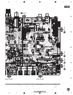
Page 93: ...93 HTP 071 5 6 7 8 5 6 7 8 A B C D E F D SIDE B CN600 CP104 ...


