16
HTP-071
1
2
3
4
A
B
C
D
E
F
1
2
3
4
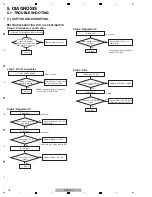
5. DIAGNOSIS
5.1 TROUBLESHOOTING
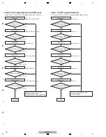
Step 0: Preliminary confirmation
confirm the following items before checking
To Step 1
To Step 3
do screws of COAX jack
securely tighten?
OR connect G
N
D wire of
DSP JIG B'D to chassis.
step 1: B to B connector
CP201, C
N
601, C
N
600
To Step 2
To Step 5
To Step 4
Turn the power off and insert
the connectors securely
Are the connectors
securely inserted?
Yes
Yes
Yes
N
o
BtoB connector
XMCK
* C
N
600 connectors doesn't connection
in case of DSP JIG B'D use.
Tighten screws securely.
N
o
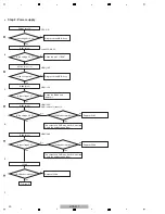
Step 2: Regulator IC
IC608 (pin 2)
IC100 (pin 2)
Is the voltage of arround
10 V input?
Check the resistor (R27, R31)
MAI
N
Assy.
N
o
Yes
Is the voltage of 3.3 V
output?
Replace IC608 or L160.
N
o
(to chassis)
(to chassis)
* If the "sub_pw" is high level to OK.
IC100 (pin 3)
Yes
Is the voltage of 1.2 V
output?
Replace IC102 or IC100.
N
o
Yes
Step 3: Regulator IC
IC609 (pin3)
Is the voltage of arround
5 V input?
Check the IC1 (pin 3) of
MAI
N
Assy.
N
o
(to chassis)
This power is power supply of
IC601 (PCM1681).
Yes
Step 4: X'tal
IC602 (pins 39, 40)
IC102 (pin 17)
Is there a 24.576 MHz
output?
Replace XTAL101 or IC602.
N
o
Yes
Is there a 24.576 MHz
input?
Check the IC610 of pin 6 and
check the around of resistor.
N
o
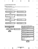
[1] DSP TROUBLESHOOTING
TROUBLESHOOTING FOR ALL DESTINATION
Summary of Contents for HTP-071
Page 9: ...9 HTP 071 5 6 7 8 5 6 7 8 A B C D E F ...
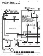
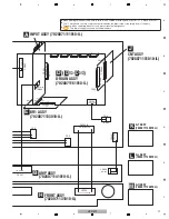
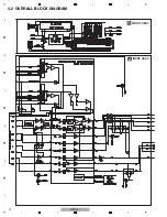
Page 12: ...12 HTP 071 1 2 3 4 A B C D E F 1 2 3 4 4 2 OVERALL BLOCK DIAGRAM H FRONT ASSY A INPUT ASSY ...
Page 89: ...89 HTP 071 5 6 7 8 5 6 7 8 A B C D E F C SIDE B CP1 CP3 CP5 CN1 CN3 ...
Page 93: ...93 HTP 071 5 6 7 8 5 6 7 8 A B C D E F D SIDE B CN600 CP104 ...


