22
HTP-071
1
2
3
4
A
B
C
D
E
F
1
2
3
4
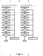
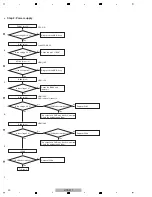
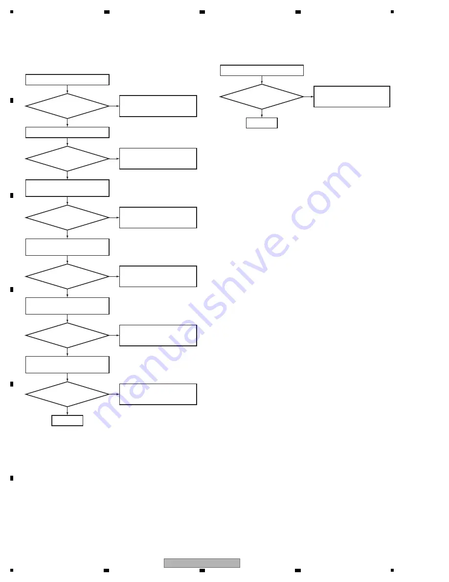
SDA (HDMI_OUT)
Check the JACK204 and IC201.
If JACK204 or IC201 is failure,
replace JACK204 or IC201.
N
o
Yes
IC201 (pin 7)
Does a signal output
in constant period
(0 to 5 V)?
SCL (HDMI_OUT)
* when connected the equipment to
I
N
1 (CD/SAT):
Check the JACK204 and IC201.
If JACK204 or IC201 is failure,
replace JACK204 or IC201.
N
o
Check the JACK201 and IC200.
If JACK201 or IC200 is failure,
replace JACK201 or IC200.
N
o
Yes
IC201 (pin 6)
Does a signal output
in constant period
(0 to 5 V)?
Is the voltage swing
0 to 5 V?
IC200 (pin 85) SDA
IC200 (pin 86) SCL
* when connected the equipment to
I
N
2 (BD):
Check the JACK202 and IC200.
If JACK202 or IC200 is failure,
replace JACK202 or IC200.
N
o
Yes
Yes
Is the voltage swing
0 to 5 V?
IC200 (pin 83) SDA
IC200 (pin 84) SCL
* when connected the equipment to
I
N
3 (DVD):
Check the JACK203 and IC200.
If JACK203 or IC200 is failure,
replace JACK203 or IC200.
N
o
Yes
Is the voltage swing
0 to 5 V?
IC200 (pin 81) SDA
IC200 (pin 82) SCL
* when connected the equipment to
I
N
4 (DVR/BDR):
Check the JACK205 and IC200.
If JACK205 or IC200 is failure,
replace JACK205 or IC200.
N
o
Yes
Is the voltage swing
0 to 5 V?
IC200 (pin 114) SDA
IC200 (pin 115) SCL
Step 6: SDA /SCL
To Step 7
TMDS OUTPUT
Check the IC1001 or IC1002.
If IC1001 or IC1002 is failure,
replace IC1001 or IC1002.
N
o
Yes
IC1002 (pins 30,31,33,34,36,37,39,40)
Are there signals
(approx. 0.5 Vp-p)
I
N
all lines?
Step 7: TMDS
End
Summary of Contents for HTP-071
Page 9: ...9 HTP 071 5 6 7 8 5 6 7 8 A B C D E F ...
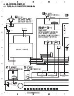
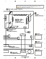
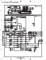
Page 12: ...12 HTP 071 1 2 3 4 A B C D E F 1 2 3 4 4 2 OVERALL BLOCK DIAGRAM H FRONT ASSY A INPUT ASSY ...
Page 89: ...89 HTP 071 5 6 7 8 5 6 7 8 A B C D E F C SIDE B CP1 CP3 CP5 CN1 CN3 ...
Page 93: ...93 HTP 071 5 6 7 8 5 6 7 8 A B C D E F D SIDE B CN600 CP104 ...


