25
HTP-071
5
6
7
8
5
6
7
8
A
B
C
D
E
F
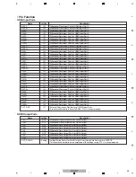
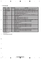
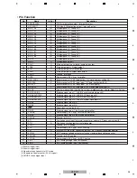
• Pin Function
Name
HDMI Input Ports
In/Out
Description
RXC0-
I
N
Differential Clock Input Pair for HDMI Input Port 0
RXC0+
I
N
Differential Clock Input Pair for HDMI Input Port 0
RX00-
I
N
Differential Data Input Pair0 for HDMI Input Port 0
RX00+
I
N
Differential Data Input Pair0 for HDMI Input Port 0
RX10-
I
N
Differential Data Input Pair1 for HDMI Input Port 0
RX10+
I
N
Differential Data Input Pair1 for HDMI Input Port 0
RX20-
I
N
Differential Data Input Pair2 for HDMI Input Port 0
RX20+
I
N
Differential Data Input Pair2 for HDMI Input Port 0
RXC1-
I
N
Differential Clock Input Pair for HDMI Input Port 1
Name
HDMI Output Ports
In/Out
Description
TXC-
OUT
Differential Clock Output Pair for HDMI Output
TXC+
OUT
Differential Clock Output Pair for HDMI Output
TX0-
OUT
Differential Data Output Pair0 for HDMI Output
TX0+
OUT
Differential Data Output Pair0 for HDMI Output
TX1-
OUT
Differential Data Output Pair1 for HDMI Output
TX1+
OUT
Differential Data Output Pair1 for HDMI Output
TX2-
OUT
Differential Data Output Pair2 for HDMI Output
TX2+
OUT
Differential Data Output Pair2 for HDMI Output
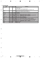
EXT_SWI
N
G
Analog
Voltage Swing Adjust for HDMI Output. A resistor should tie this pin to AVDD18.
This resistance determines the amplitude of the voltage swing. 270
Ω
is recommended.
RXC1+
I
N
Differential Clock Input Pair for HDMI Input Port 1
RX01-
I
N
Differential Data Input Pair0 for HDMI Input Port 1
RX01+
I
N
Differential Data Input Pair0 for HDMI Input Port 1
RX11-
I
N
Differential Data Input Pair1 for HDMI Input Port 1
RX11+
I
N
Differential Data Input Pair1 for HDMI Input Port 1
RX21-
I
N
Differential Data Input Pair2 for HDMI Input Port 1
RX21+
I
N
Differential Data Input Pair2 for HDMI Input Port 1
RXC2-
I
N
Differential Clock Input Pair for HDMI Input Port 2
RXC2+
I
N
Differential Clock Input Pair for HDMI Input Port 2
RX02-
I
N
Differential Data Input Pair0 for HDMI Input Port 2
RX02+
I
N
Differential Data Input Pair0 for HDMI Input Port 2
RX12-
I
N
Differential Data Input Pair1 for HDMI Input Port 2
RX12+
I
N
Differential Data Input Pair1 for HDMI Input Port 2
RX22-
I
N
Differential Data Input Pair2 for HDMI Input Port 2
RX22+
I
N
Differential Data Input Pair2 for HDMI Input Port 2
RXC3-
I
N
Differential Clock Input Pair for HDMI Input Port 3
RXC3+
I
N
Differential Clock Input Pair for HDMI Input Port 3
RX03-
I
N
Differential Data Input Pair0 for HDMI Input Port 3
RX03+
I
N
Differential Data Input Pair0 for HDMI Input Port 3
RX13-
I
N
Differential Data Input Pair1 for HDMI Input Port 3
RX13+
I
N
Differential Data Input Pair1 for HDMI Input Port 3
RX23-
I
N
Differential Data Input Pair2 for HDMI Input Port 3
RX23+
I
N
Differential Data Input Pair2 for HDMI Input Port 3
EXT_RES
I
N
External Termination Resistor for all HDMI Input Ports.
A resistor should tie this pin to AVDD33. 470
Ω
is recommended.
Summary of Contents for HTP-071
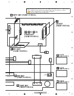
Page 9: ...9 HTP 071 5 6 7 8 5 6 7 8 A B C D E F ...
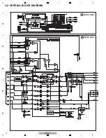
Page 12: ...12 HTP 071 1 2 3 4 A B C D E F 1 2 3 4 4 2 OVERALL BLOCK DIAGRAM H FRONT ASSY A INPUT ASSY ...
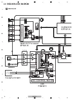
Page 89: ...89 HTP 071 5 6 7 8 5 6 7 8 A B C D E F C SIDE B CP1 CP3 CP5 CN1 CN3 ...
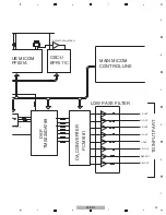
Page 93: ...93 HTP 071 5 6 7 8 5 6 7 8 A B C D E F D SIDE B CN600 CP104 ...

