36
HTP-071
1
2
3
4
A
B
C
D
E
F
1
2
3
4
6. SERVICE MODE
6.1 SERVICE MODE
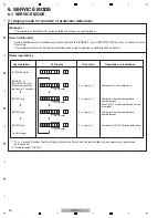
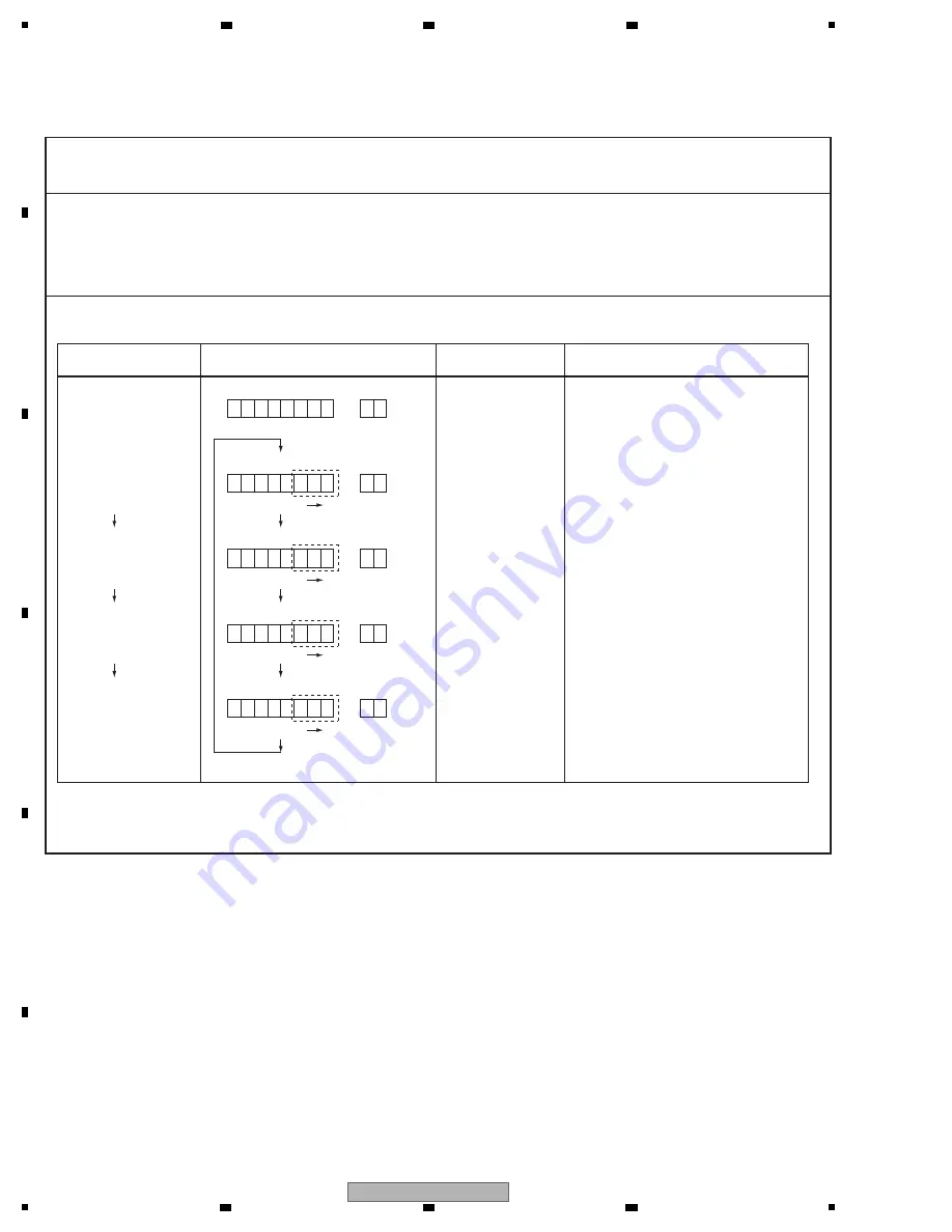
[1] Display mode for numbers of protection detections
[Purpose]
[Basic operations]
FL Display
Description of Indications
Key Operation
(STA
N
DBY state)
[PRESET –] +
[STA
N
DBY/O
N
] keys
(Initial display)(press
the keys for 2 seconds.)
[E
N
TER] key
(Initial display)
5 (-> normal) *1
5 (-> normal) *1
N
umber of DC error detections
N
umber of abnormal-temperature
error detections
N
ote:TEMP1 is displayed, but do not use
this model.
Time (sec.)
The numbers of detections for various protection processes are displayed.
*1 "5 (-> normal)" denotes that the display will return to the normal indication when no key operation is performed
for 5 seconds.
*2 Variable range: 0 to 255
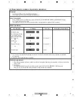
[How to enter/exit]
During Standby mode, simultaneously press and hold the [PRESET –] and [STA
N
DBY/O
N
] keys for 2 seconds to enter
this mode.
The display will return to the normal indication when no key operation is performed for 5 seconds.
Counter
D C
: 0 0 5
Counter
T M P 1 : 0 0 3
[E
N
TER] key
5 (-> normal) *1
N
umber of abnormal-temperature
error detections
Counter
T
O
M P 2 : 0 0 3
[E
N
TER] key
5 (-> normal) *1
N
umber of OVERLOAD error detections
Counter
V E R : 0 0 3
Summary of Contents for HTP-071
Page 9: ...9 HTP 071 5 6 7 8 5 6 7 8 A B C D E F ...
Page 12: ...12 HTP 071 1 2 3 4 A B C D E F 1 2 3 4 4 2 OVERALL BLOCK DIAGRAM H FRONT ASSY A INPUT ASSY ...
Page 89: ...89 HTP 071 5 6 7 8 5 6 7 8 A B C D E F C SIDE B CP1 CP3 CP5 CN1 CN3 ...
Page 93: ...93 HTP 071 5 6 7 8 5 6 7 8 A B C D E F D SIDE B CN600 CP104 ...


