40
HTP-071
1
2
3
4
A
B
C
D
E
F
1
2
3
4
2. Notes on Disassembly and Reassembly
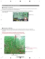
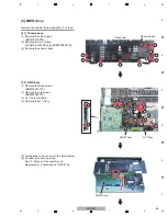
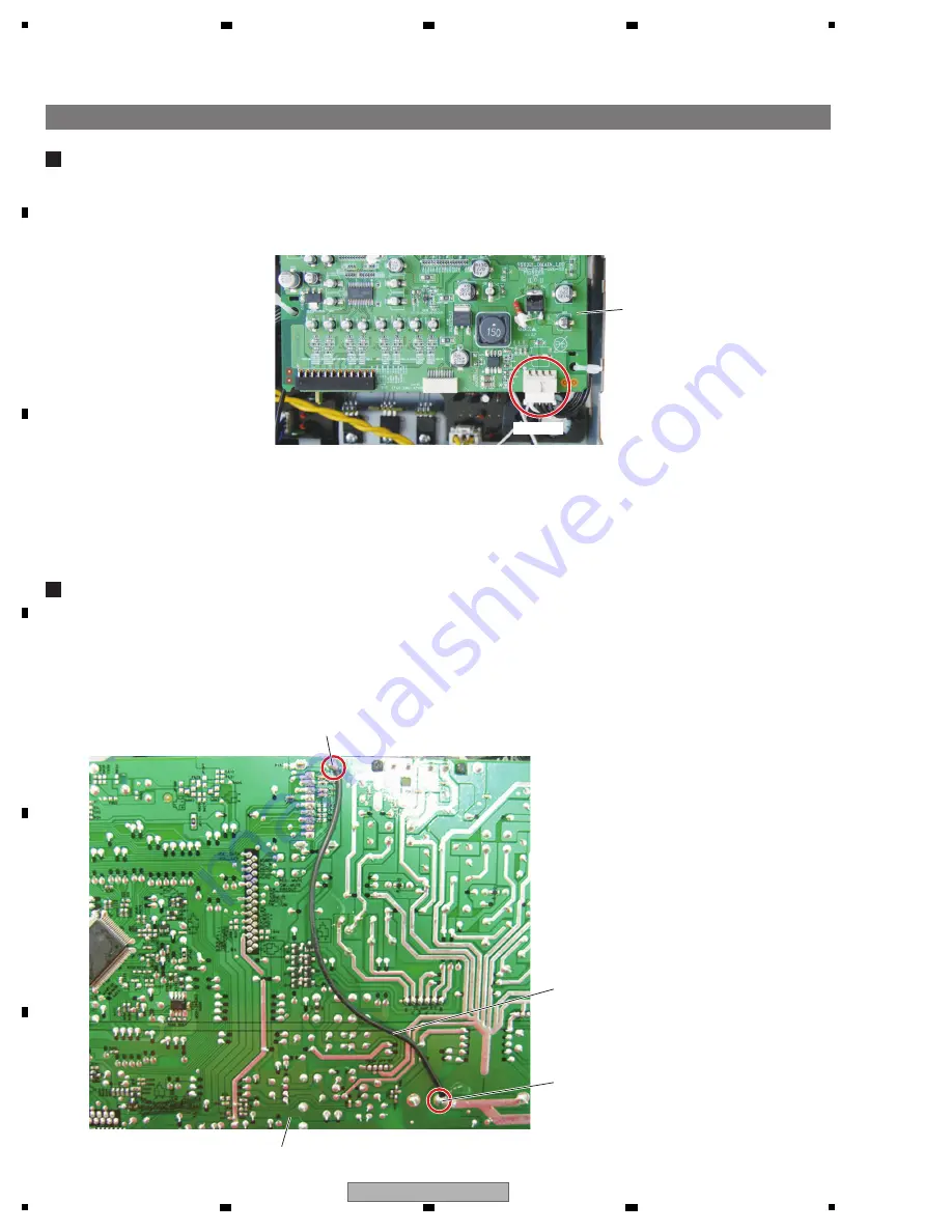
During repair, before checking the MAI
N
Assy, etc., with the rear chassis removed, be sure to connect the
G
N
D terminal of the main capacitor to the chassis back (Tuner pack chassis), as shown below, then connect the
power cord.
Without grounding connection, the protection circuit will be activated.
After repairing, be sure to remove the ground wire before reassembling.
Main capacitor G
N
D
MAI
N
Assy (SIDE B)
Tuner pack chassis
D-MAI
N
Assy
G
N
D wire
(Be sure to disconnect the G
N
D wire
before reassembly.)
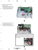
After completion of reassembly, before plugging the power cord into an outlet, make sure that the 4P wires from C
N
5 of
the MAI
N
Assy are connected to CP104 of the D-MAI
N
Assy.
If the unit is turned ON without these wires connected, the CODEC IC (IC602) on the D-MAIN Assy
may be damaged.
Confirmation of Connection
CP104
Confirmation of GND Wire
Summary of Contents for HTP-071
Page 9: ...9 HTP 071 5 6 7 8 5 6 7 8 A B C D E F ...
Page 12: ...12 HTP 071 1 2 3 4 A B C D E F 1 2 3 4 4 2 OVERALL BLOCK DIAGRAM H FRONT ASSY A INPUT ASSY ...
Page 89: ...89 HTP 071 5 6 7 8 5 6 7 8 A B C D E F C SIDE B CP1 CP3 CP5 CN1 CN3 ...
Page 93: ...93 HTP 071 5 6 7 8 5 6 7 8 A B C D E F D SIDE B CN600 CP104 ...


