41
HTP-071
5
6
7
8
5
6
7
8
A
B
C
D
E
F
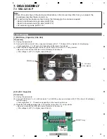
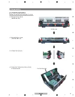
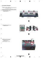
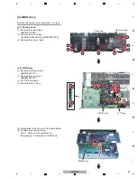
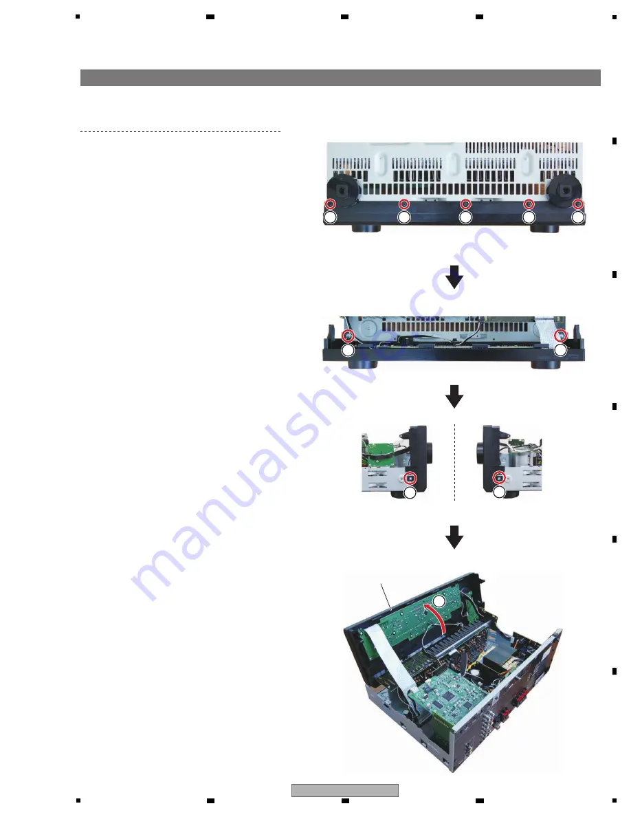
[1] Front Panel Section
Remove the cabinet by removing the 10 screws.
(1) Remove the five screws.
(BBZ30P080FTB)
(2) Remove the two screws.
(1500001206010-IL)
(3) Unhook the two hooks.
(4) Arrange the front panel section as shown
in the photo below.
1
1
1
1
1
2
3
3
2
4
• Bottom view
Front panel section
3. Disassembly
Summary of Contents for HTP-071
Page 9: ...9 HTP 071 5 6 7 8 5 6 7 8 A B C D E F ...
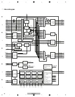
Page 12: ...12 HTP 071 1 2 3 4 A B C D E F 1 2 3 4 4 2 OVERALL BLOCK DIAGRAM H FRONT ASSY A INPUT ASSY ...
Page 89: ...89 HTP 071 5 6 7 8 5 6 7 8 A B C D E F C SIDE B CP1 CP3 CP5 CN1 CN3 ...
Page 93: ...93 HTP 071 5 6 7 8 5 6 7 8 A B C D E F D SIDE B CN600 CP104 ...

