42
HTP-071
1
2
3
4
A
B
C
D
E
F
1
2
3
4
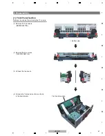
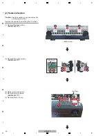
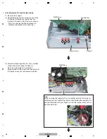
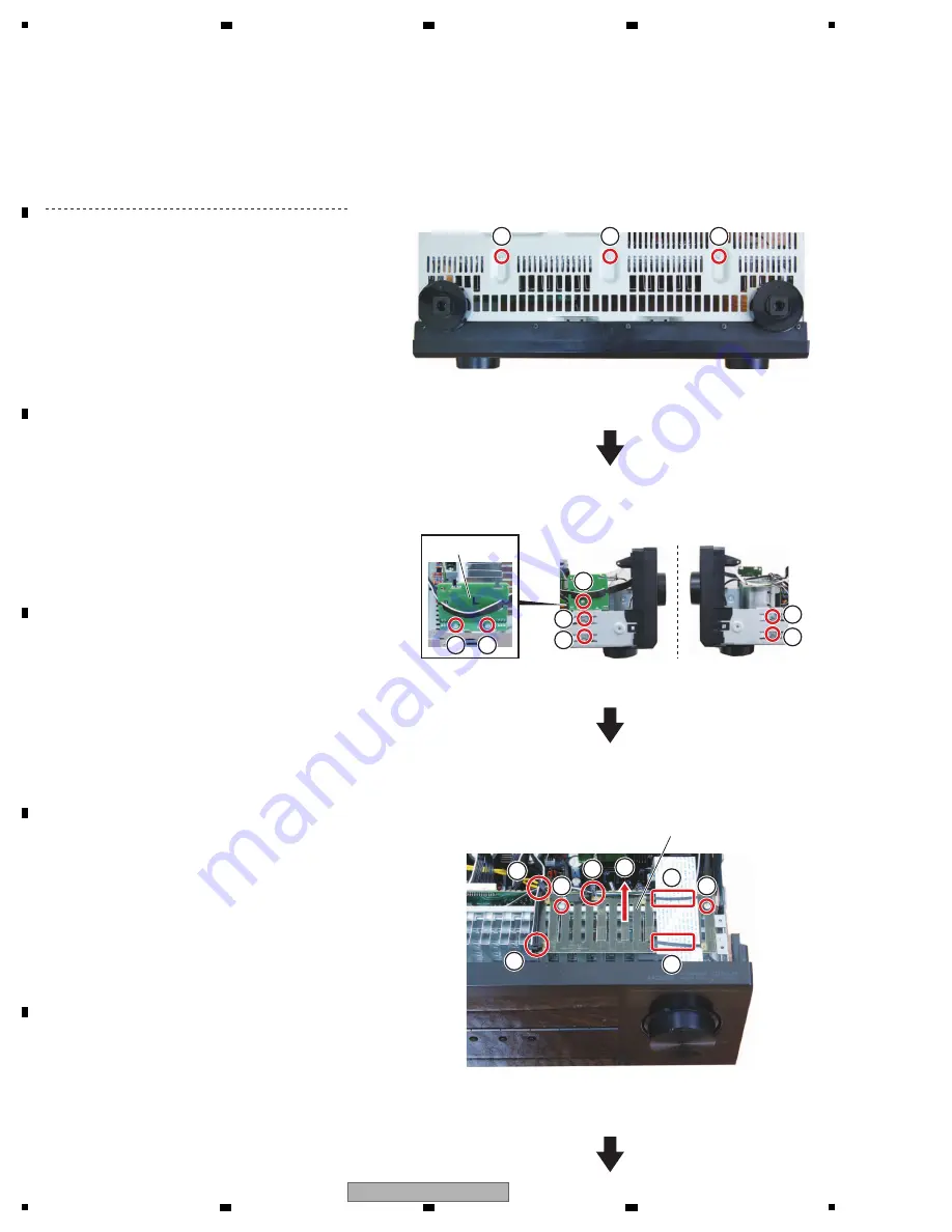
[2] Heatsink Section
Remove the cabinet by removing the 10 screws.
Caution:
Heatsink section in work becomes hot,
and be careful with it.
(1) Remove the three screws.
(BBZ30P080FTC)
(2) Remove the seven screws.
(BBZ30P080FTC)
(3) Release the five binders.
(4) Remove the two screws.
(BBZ30P080FTC)
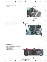
(5) Remove the G-H Assy.
1
1
1
2
2
2
4
4
2
2
2
2
• Bottom view
G-H Assy
G-L Assy
5
3
3
3
3
3
Summary of Contents for HTP-071
Page 9: ...9 HTP 071 5 6 7 8 5 6 7 8 A B C D E F ...
Page 12: ...12 HTP 071 1 2 3 4 A B C D E F 1 2 3 4 4 2 OVERALL BLOCK DIAGRAM H FRONT ASSY A INPUT ASSY ...
Page 89: ...89 HTP 071 5 6 7 8 5 6 7 8 A B C D E F C SIDE B CP1 CP3 CP5 CN1 CN3 ...
Page 93: ...93 HTP 071 5 6 7 8 5 6 7 8 A B C D E F D SIDE B CN600 CP104 ...


