43
HTP-071
5
6
7
8
5
6
7
8
A
B
C
D
E
F
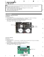
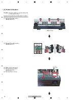
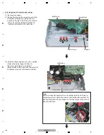
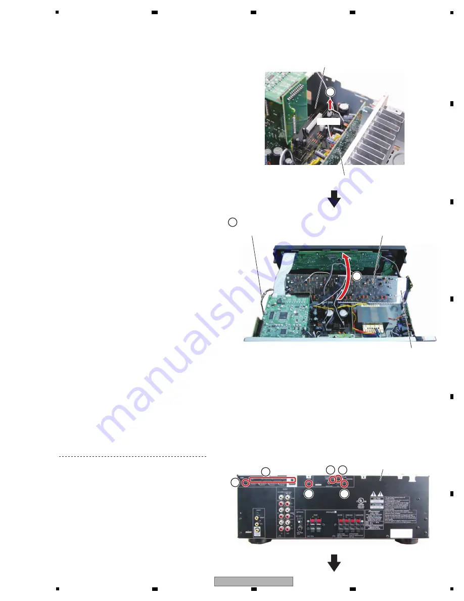
(6) Disconnect the one connector.
(CP404)
(7) Connect the extension jig cable.
(AMP
C
N
203
↔
MAI
N
CP404)
(8) Rotate the heatsink section in the direction of
the
arrow.
MAI
N
Assy
AMP Assy
AMP Assy
Heatsink
7
8
CP404
Extension jig cable
(GGD1773)
6
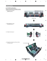
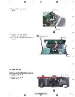
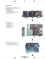
[3] D-MAIN Assy
Remove the cabinet by removing the 10 screws.
(1) Remove the five screws.
(BBT30P100FTB)
(2) Remove the five screws.
(BSZ30P040FTB)
• Rear view
Chassis back
1
1
1
1 1
2
×
5
Summary of Contents for HTP-071
Page 9: ...9 HTP 071 5 6 7 8 5 6 7 8 A B C D E F ...
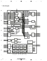
Page 12: ...12 HTP 071 1 2 3 4 A B C D E F 1 2 3 4 4 2 OVERALL BLOCK DIAGRAM H FRONT ASSY A INPUT ASSY ...
Page 89: ...89 HTP 071 5 6 7 8 5 6 7 8 A B C D E F C SIDE B CP1 CP3 CP5 CN1 CN3 ...
Page 93: ...93 HTP 071 5 6 7 8 5 6 7 8 A B C D E F D SIDE B CN600 CP104 ...


