46
HTP-071
1
2
3
4
A
B
C
D
E
F
1
2
3
4
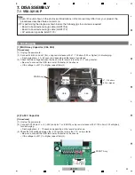
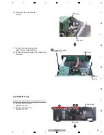
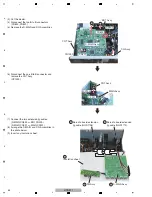
[4-3] Regulator ICs and Recifier diode
(1) Remove the support.
(2) Tighten then loosen the screw in each of the
four holes for temporary joining that are
located on the rear side of the main chassis.
(This is for shaving the thread grooves to
facilitate attachment in the next step.)
Support
Main chassis
1
2
2
2
2
MAI
N
Assy
Screwdriver
(3) Attach the three regulator ICs and a rectifier
diode to the holes tapped in Step (2).
Be sure to place them in a direction
perpendicular to the board and take care that
the jumper wires will not become distorted.
N
ote:
While securing the regulator ICs and rectifier diode to the holes for
temporary joining, tighten the screws while holding the regulator ICs
and rectifier diode with your fingers so that the jumper wires will not
become distorted.
MAI
N
Assy
3 3 3
3
Summary of Contents for HTP-071
Page 9: ...9 HTP 071 5 6 7 8 5 6 7 8 A B C D E F ...
Page 12: ...12 HTP 071 1 2 3 4 A B C D E F 1 2 3 4 4 2 OVERALL BLOCK DIAGRAM H FRONT ASSY A INPUT ASSY ...
Page 89: ...89 HTP 071 5 6 7 8 5 6 7 8 A B C D E F C SIDE B CP1 CP3 CP5 CN1 CN3 ...
Page 93: ...93 HTP 071 5 6 7 8 5 6 7 8 A B C D E F D SIDE B CN600 CP104 ...

