50
HTP-071
1
2
3
4
A
B
C
D
E
F
1
2
3
4
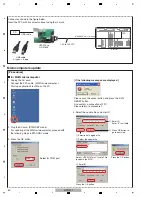
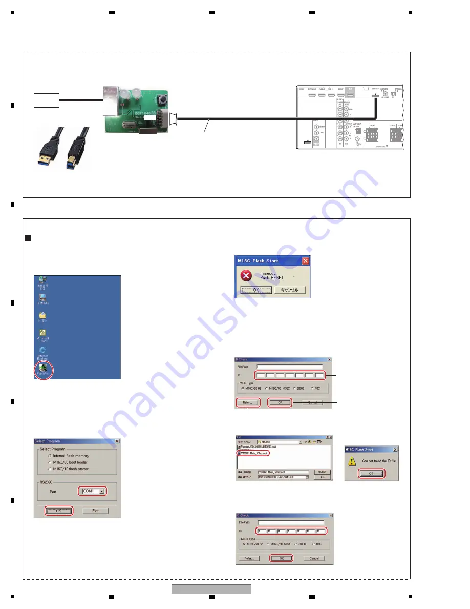
Microcomputers update
PC
UPDATE jig
GGF1646
USB cable
A type <-> B type
USB cable
Rear side
(HDMI/CEC microcomputer)
10P
10P
Connect as shown in the figure below.
Insert the FFC with its contact surface facing the
"
mark.
[Procedures]
for MAIN microcomputer
1. Unplug the AC cord.
Connect the FFC cable. ( MAI
N
microcomputer )
Start up application FlashSta on the PC.
3. Press the OK button.
[ if the following messages are displayed ]
Please push the cancel button and press the JIG's
RESET button.
And confirm a connection of FFC.
Please return to procedure 1.
2. Plug the AC cord. (STA
N
DBY mode)
For updating of the MAI
N
microcomputer, proceed with
the following steps in STA
N
DBY mode.
10P to 10P FFC
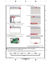
Select for COM port.
4. Select the update file and enter ID.
1
Selection of upgrade file
1
Select the update file
2
Enter ID.
Select "VSX321 Main V1xx.mot" file
to update the MCU.
2
Enter ID.
Enter "ff" in all field.
Press the OK button.
Press the OK button.
3
Press OK button to
go to next step.
Summary of Contents for HTP-071
Page 9: ...9 HTP 071 5 6 7 8 5 6 7 8 A B C D E F ...
Page 12: ...12 HTP 071 1 2 3 4 A B C D E F 1 2 3 4 4 2 OVERALL BLOCK DIAGRAM H FRONT ASSY A INPUT ASSY ...
Page 89: ...89 HTP 071 5 6 7 8 5 6 7 8 A B C D E F C SIDE B CP1 CP3 CP5 CN1 CN3 ...
Page 93: ...93 HTP 071 5 6 7 8 5 6 7 8 A B C D E F D SIDE B CN600 CP104 ...

