51
HTP-071
5
6
7
8
5
6
7
8
A
B
C
D
E
F
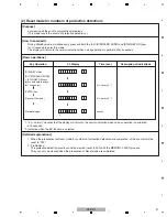
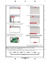
6. Update Finished MAI
N
microcomputer.
7. Unplug the AC cord.
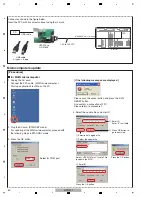
Disconnect the FFC cable.
5. Set speed update and update the MCU.
Press the OK button.
Set Baud rate to 38400.
Press the OK button.
Press the Exit button.
Please wait for until this window
disappears.
When the PC and the Upgrade Jig is connecting,
the COM PORT is set automatically.
Push the JIG’s RESET button during
1 sec.
Press the OK button.
Select the 9600 of the Board rate then
press the OK button
2
Update the MCU.
E.P.R=>Erase+Read
2
Update the MCU
Press the E.P.R … button
1
Set speed of update.
1
Set speed of update.
Press OK button.
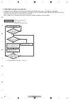
If the following messages are displayed, shut the update
program down, and start the update again from step 1.
for HDMI (SUB) microcomputer
8. Unplug the AC cord.
Start up the application EPFlash on the PC.
9. Select "HDMI UP" on the Upgrade Jig.
10. While holding down the tact switch of the Upgrade Jig,
press
STA
N
DBY/O
N
button.
After 2 or 3seconds, release the tact switch button.
Connect the PC and the Upgrade Jig.
Connect the FFC cable. (HDMI microcomputer )
Plug the AC cord. (STA
N
DBY mode)
Summary of Contents for HTP-071
Page 9: ...9 HTP 071 5 6 7 8 5 6 7 8 A B C D E F ...
Page 12: ...12 HTP 071 1 2 3 4 A B C D E F 1 2 3 4 4 2 OVERALL BLOCK DIAGRAM H FRONT ASSY A INPUT ASSY ...
Page 89: ...89 HTP 071 5 6 7 8 5 6 7 8 A B C D E F C SIDE B CP1 CP3 CP5 CN1 CN3 ...
Page 93: ...93 HTP 071 5 6 7 8 5 6 7 8 A B C D E F D SIDE B CN600 CP104 ...

