8
3
HTP-071
5
6
7
8
5
6
7
8
A
B
C
D
E
F
A
A
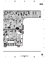
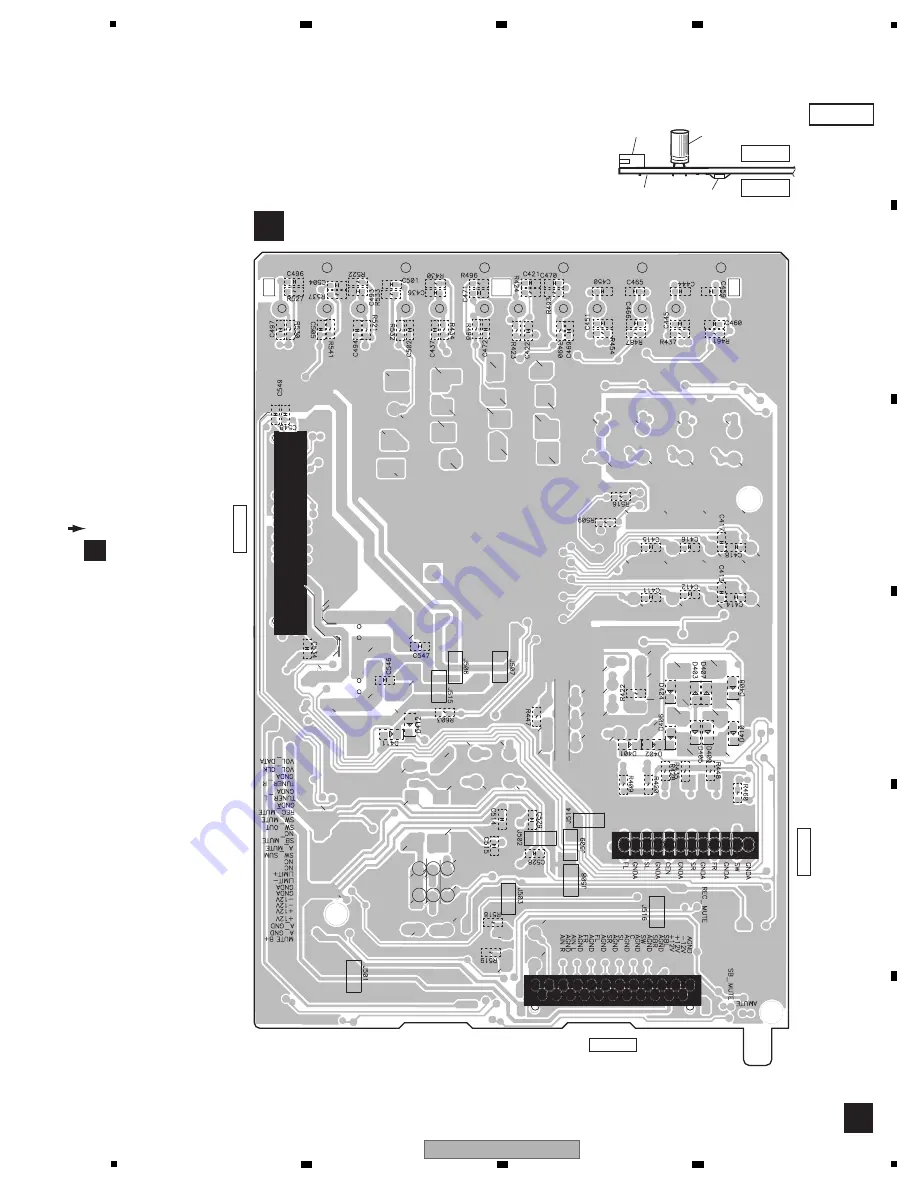
INPUT ASSY
SIDE B
CP400
C
CP17
CP401
C
N
400
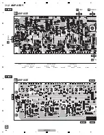
NOTE FOR PCB DIAGRAMS :
1. The parts mounted on this PCB include all
necessary parts for several destinations.
For further information for respective desti-
nations, be sure to check with the sche-
matic diagram.
Capacitor
Connector
P.C.Board
Chip Part
SIDE A
SIDE B
2. View point of PCB diagrams.
Summary of Contents for HTP-071
Page 9: ...9 HTP 071 5 6 7 8 5 6 7 8 A B C D E F ...
Page 12: ...12 HTP 071 1 2 3 4 A B C D E F 1 2 3 4 4 2 OVERALL BLOCK DIAGRAM H FRONT ASSY A INPUT ASSY ...
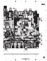
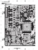
Page 89: ...89 HTP 071 5 6 7 8 5 6 7 8 A B C D E F C SIDE B CP1 CP3 CP5 CN1 CN3 ...
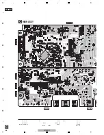
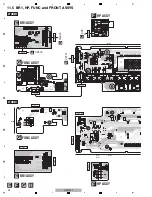
Page 93: ...93 HTP 071 5 6 7 8 5 6 7 8 A B C D E F D SIDE B CN600 CP104 ...

