background image

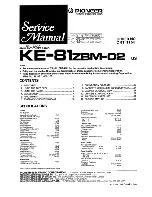
Summary of Contents for KE-81ZBM-02

Page 1: ...N S FN IOjlV Signal Noise Ratio 5 mV 50 dB Selectivity 10 kHz lOqdB IF Rejection 100 dB Image Rejection 60 dB Distortion 5 mV RF 0 5 Frequency Range 530 to 1620 kHz Intermediate Frequency 450 kHz WB Receiver Usable Sensitivity Load 20 dB S FN S l N FD 0 3 iV Signal Noise Ratio 1 mV 55 dB Distortion 1 5 Frequency Range 162 400 to 162 550 MHz Intermediate Frequency 1st I F 25 kHz Step 10 7MHz 2nd I ...

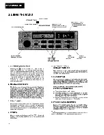
Page 2: ...er 42 Instead of 43 continue the code number sequence of 215 to complete that entry In this case a beep will sound to signal input of the 5 dlgit code the word code will remain on the display and the radio will not operate Re enter the correct number sequence of 43215 and operation of the radio will continue The likelihood of guessing the correct code is extremely remote The radio Is therefore uns...

Page 3: ...igh frequency response By not using the Dolby NR func tion with Dolby NR encoded tapes the high frequency response will be intensified The symbol will appear on the display when the Dolby NR button is pressed 6 TAPE EJECT T1I Press the eject EJ button to eject tape cassette and return to the radio mode 7 AUTOMATIC EQUALIZATION The playback equalization of NORMAL tapes differs from CHROME CrOg and ...

Page 4: ...frequency 3 SCAN TUNING When the on off volume control knob Is pressed scann ing begins upscale from station to station pausing seven seconds at each medium to strong frequency Scanning stops when the volume knob is pressed again during the seven second pause 4 STEREO When a stereo station is received the ST indicator will light up on the display It will flash when the signal strength diminishes 5...

Page 5: ...ig 2 Grille Assy 1 Insert a screwdriver and turn it in the arrow direc tion then two connector catches come off and the flexible circuit board can be removed 2 Remove three knobs and remove two screws 3 Press tabs at two locations indicated by arrows and pull out grille assy Fig 3 Chassis Unit 1 Remove four screws 2 Unbend tabs at location indicated by arrow 3 Raise up on tuner amp unit to remove ...

Page 6: ......

Page 7: ...5MHz NOTE After adjusting L803 disconnect frequency counter 2 162 400 60 NB Volume control knob mV Meter 2 10dBs 3 162 400 60 m L808 Distortion Meter Minimum 4 162 400 60 WB L807 Distortion MeteriMinimum 5 Repeat No 3 4 alternately so that the distortion meter indicates minimum 6 162 475 10 15 WB L801 L802 mV Meter 2 Maximum 7 162 475 10 15 WB L804 mV Me ter 2 Maxi mum 8 If L804 is adjusted more t...

Page 8: ...vss ...

Page 9: ... 81ZBM f A9C SIGNAL ARC NOISE Adi METER time out in 10 ...

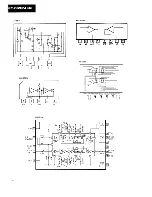
Page 10: ...KE B1ZBM OS AN6540 M51522AL ...

Page 11: ...lecting gear 18 OUT GND GND terminal of the motor drive circuit 19 CMH Output H terminal drive output of capstan motor M3 Output voltage During speed control approx Vcc 1 7V During LOAD or EJECT 6 9V 20 CMR Output R terminal drive output of capstan motor M3 1 During speed control OPEN 2 During LOAD approx OV 3 During EJECT approx 7V 21 CMG Output GND terminal drive output of capstan motor M3 1 Dur...

Page 12: ...olby NR Is on 24 ANTI 1 Output Causes LED to flash when Anti Theft is operating 25 ANTI 2 Output H when Anti Theft is displayed 26 MS Input MS input 27 12 Output 28 11 Output IC601 control data terminal 29 10 Output 30 SO Output Serial data output 31 SCK Output Serial clock signal output 32 SI Input Input for serial data from IC702 33 VDD Power supply terminal 5V 34 END2 SD Input Tape mode Reverse...

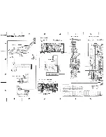
Page 13: ...KE B1ZBM OS 6 SCHEMATIC CIRCUIT 2 DIAGRAM 3 4 5 6 A B C D 1 2 3 4 5 6 ...

Page 14: ... SET SWITCH ON OFF S2 CST IN SWITCH OFF S3 70 iS SWITCH ON 120 S OFF 70 S The under lined indicates the switch position 1 Tuner Amp Unit KE 81ZBM 02 I 1 Consists of 1 1 Mother P C Board 1 AM P C Board 1 WB P C Board 1 1 Dolby NR P C Board 1 Lamp P C Board Back Up P C Board 1 FM Front End CWB1004 1 1 B C D Fig 7 7 10 1 11 12 1 1 1 J 1 1 1 1 ...

Page 15: ...ARD Q804 IC801 ADJL807 L808 L806 SWITCH P C BOARD M Q802 Q803 Q801 L804 L802 L803 L801 L804 AM P C BOARD Q204 1C Q Q202 Q201 IC201 Q203 ADJ T205 T204 T206 T203 T207 MOTHER P C BOARD IC Q IC51 ADJ VR51 T51 IC501 Q Q705 Q702 Q601 ICl ...

Page 16: ...l 0K fw S Frf in SI3sv2 i R6S6 fC7b5 i g f pi m 06 C705 it C711 V 13724 rtiM dIfeTjSv f jw J J nnnJ Rgoa R9 m i T 54 i R92 r l OlO N l 8 27 25 23 2 11 18 10 4 2 r i i T T 7 1 1fcS222 2SsS3222 I TZ M p 6 ml Uf m Q452 Jl t T I t V W ftflsa js f 7 SCAN PROGRAM VRS51 2 I L IVbLUME R L Ui W W 8 J CS03 4i i R93S _ 7 R 5 f 1 I l F UULvo ume u 3 or POWER 10 11 12 KE 81ZBM 08 BACK UP P C BOARD BACK UP B IL...

Page 17: ...8 CASSETTE MECHANISM EXPLODED VIEW A Parts List NOTE For your p marks if ir a if if GENER This dassifh model numi Parts whose Parts marke longer than Mark No ...

Page 18: ...F 126 Washer 46 PMS26P025FMC Screw 13 CBH 835 Spring 47 CBH 830 Spring 14 CBG1003 E Type Washer 48 HBA 175 Screw M2x2 5 15 CBH 832 Spring 49 Spacer 16 CXA1445 Pinch Roller Unit 50 CBL1050 Spring 17 CBH 834 Spring 51 CBF1025 Washer 18 YE25FUC E Type Washer 52 19 CNV1254 Arm 53 CBH 893 Spring 20 CBF1022 Washer 54 CLAlllO Collar 21 CNW 932 Collar 55 Clamper 22 CBH 827 Spring 56 CNV1616 Gear 23 CXD208...

Page 19: ......

Page 20: ...12 CAC1378 Knob B 13 BPZ20P060FZK Screw 14 CWM1145 Key Board Unit 15 P C Board Mark No _Part No Description 21 IN81RC5V LED 22 LN12GC56 LED 23 CSG1004 Swi tch 24 CNM1080 Spacer 25 CAC1376 Button BAND 26 CAC1373 But ton 3 27 CAC1371 Button 1 28 CAC1374 But ton 4 29 CAC1372 But ton 2 30 CAC1375 Button 5 31 CXA1347 Case Unit S 32 CXK1651 Cassette Mechanism Assy 33 Lens 16 CNV1103 Housing 17 CSHlOOl S...

Page 21: ......

Page 22: ...5 Holder 50 Plug 16 EBR3432S LED 51 Heat Sink 17 Plug 52 Plug 18 CEL1003 Lamp 14V 40mA 53 CEK1009 Fuse 2A 19 Spacer 54 CDE1159 Connector 20 AA3433S LED 55 AN6540 IC 21 Connector 56 Frame 22 CEL1019 Lamp 8V 60mA 57 BMZ26P030FMC Screw 23 CNV1207 Holder 58 Connector 24 CNV1144 Holder 59 Insulator 25 CNM1155 Sheet 60 Case 26 CNV1454 Connector 61 2SK241 Transistor C 27 CCS1016 Volume TREBLE BASS 62 CTX...

Page 23: ...1J R 12 RS1 8S331J R 13 RD1 4PS680JL RD1 6PS680J CAPACITORS Mark Circuit Symbol No Part Name Part No C 1 CCSSH330J50 C 2 CCSSH390J50 C 3 CCSCH060D50 CCSCH060C50 C 4 CCSTH060C50 n 1C 1 U 1C 2 n Q 1 n 2 t D 1 L 1 CW1015 CWW 173 PA4009 2SK241 2SC2753 2SC2570 KV1310A 3 aciool CTC1002 acioo3 5 11 15 20 6 7 10 C 9 C 12 18 C 13 C 14 C 16 19 21 L 4 Inductor CTF 185 q 17 T 1 Coil CTC1005 C 22 T 2 Coil aC10...

Page 24: ...04 206 207 251 1SS133 n Fuse 2A CEK1009 451 452 453 454 502 503 601 651 652 653 1SS176 701 702 703 755 756 758 759 802 803 905 US1040M RESISTORS 907 906 908 909 910 911 912 917 Mark Circuit Symbol No Part Name Part No i D 205 KV1235Z3 S D 55 1 760 913 RD6R8JSB2 R 51 453 653 933 RD1 4PS101JL HZS6R8JB2 R 52 569 570 901 902 903 904 905 932 RD1 4PS221JL t D 654 757 RD6R2JSB2 R 53 507 651 658 701 921 R...

Page 25: ...6 770 774 776 778 922 RD1 4PS103JL C 256 CEA220M16LS R 737 RS1 8S105J C 257 258 CQMA103J50LL R 755 758 926 RD1 4PS100JL C 261 CEAlOimOLL R 759 RD1 2PS821JL C 301 CEA221M10L2 R 801 RD1 4PS223JL C 302 CEA101M10L2 R 802 RD1 4PS562JL C 451 765 CEA470M16LS R 803 RD1 4PS102JL C 453 454 CEA4R7M16NPLL R 804 809 811 RD1 4PS331JL C 501 553 554 CKCYB821K50 R 805 810 RD1 4PS470JL C 503 504 509 CKSYB103K50 R 8...

Page 26: ...ESISTORS Mark Circuit Symbol No Part Name Part No MISCELLANEOUS Mark Circuit Symbol No Part Name Part No D 920 921 922 923 924 LED LN12GC56 D 925 926 927 928 929 LED LN81RC5V D 930 931 LED AA3433S n S 4 5 6 7 8 9 Sw i tch CSG1004 Unit Number I Unit Name I Switch P C Board Mark Circuit Symbol No Part Name Part No n s 1 SwitcKCST SET CSN 089 n s 2 3 SwitchCCST IN 70 iS CSN1003 MR 1 2 Magnetic Resist...

Page 27: ...ft Radio Installation Instructions 2 CRB1031 Anti Theft Program Instructions and identification Card 3 1 CRY1005 Envelope 3 2 Label 3 3 Film 3 4 CRY1003 Card 3 5 CRV1014 Label 3 6 CRW1009 Tag 4 CHP1030 5 6 CHG1336 7 CHW1009 8 CHL1336 Styrofoam Polyethylene Bag Carton Paper Sheet Contain Box 3B ...

Reviews: