background image

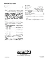
SPECIFICATIONS


Semiconductors


Transistors   ...................................................................    55


Diodes............................................................................    51


Amplifier Section


Circuitry . . .  First stage current mirror loaded, Three-stage


Darlington, Parallel push-pull, Pure complementary


OCL (class AB operation)


Continuous Power Output of 120 watts* per 

channel, min., at 8 ohms from 5 Hertz to 

30,000 Hertz with no more than 0.01 

total 

harmonic distortion, or 120 watts per channel 

at 4 ohms from 5 Hertz to 20,000 Hertz 

with no more than 0.02% total harmonic 

distortion.


Total Harmonic Distortion (20 Hertz to 20,000 Hertz, 
8 ohms)


    Continuous rated power output. .No more than 0.0 08% 
Total Harmonic Distortion (5 Hertz to 30,000 Hertz,  
8 ohms)


    Continuous rated power output. .   No more than 0.01%         

60 watts per channel


         power output.. ...................... . No more than 0.008%


    1 watt per channel


         power output............................No more than 0.008%


Intermodulation Distortion (50 Hertz : 7,000 Hertz=4:1)     

Continuous rated power output . . No more than 0.006% 
60 watts per channel


         power output............................No more than 0.005%


    1 watt per channel


         power output............................No more than 0.005%


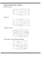
Frequency Response . .  5 Hertz to 200,000 Hertz 

+0

/

-1

dB


Input (Sensitivity / Impedance) .................. 1V/50 kilohms


Output


     Speaker...............................................4 ohms to 16 ohms


Damping Factor (5 Hertz to 30,000 Hertz, 8 ohms). . .   .60 
Hum and Noise (IHF, short-circuited, A network) . . 120dB


Miscellaneous


Power Requirements ................................ 120V, 60Hz only


Power Consumption ................................... 320 watts (UL)


Dimensions..........................420(W) x 153(H) x 370(D)mm


16-9/16 x 6 - 1 / 3 2 x 1 4-9/16 in.


Weight   without package .................... 23.5kg; 51 lb 11 oz


with package ..........................26.2kg; 57 Ib 10oz


Furnished Parts


Connection Cord with Pin Plugs   ....................................    1


Operating Instructions .....................................................    1


*Measured pursuant to Federal Trade Commission's Trade 

Regulation rule on Power Output Claims for Amplifiers.


NOTE:


Specifications and the design subject to possible modifica-

tion without notice due to improvements.


Summary of Contents for M-25

Page 1: ...Maintenance 6 Characteristics Charts 7 Specifications 8 IMPORTANT NOTICE The serial number for this equipment is located on the bottom plate Please write this serial number on your enclosed warranty card and keep in a secure area This is for your security WARNING TO PREVENT FIRE OR SHOCK HAZARD DO NOT EXPOSE THIS APPLIANCE TO RAIN OR MOISTURE ...

Page 2: ...excellent regulation but also have plenty of reserve Along with the wide band frequency response they ensure a superior channel separa tion and a reproduction of sound which is both clear and full of latent energy There is also a surge killer circuit to keep the inrush current from the power transformers as well as the high current which charges the electrolytic capacitors to the bare minimum and ...

Page 3: ......

Page 4: ...speaker to the M 25 s L speaker output terminals Both speakers are clearly marked with plus and minus polarities red and white respectively The M 25 s speaker output terminals are similarly marked Make sure that you connect like poles plus to plus minus to minus PREAMPLIFIER As shown in Fig 2 use the accessory connecting cords to connect the stereo preamplifier s output terminals to the M 25 s inp...

Page 5: ...er PROTECTIVE CIRCUITRY There will be no sound from the speakers for between three and eight seconds after the M 25 s power switch has been thrown This is because the supply of power actuates the muting circuit which is designed to eliminate noise when this switch is thrown In addition the protective circuitry is actuated to safeguard the speakers from being damaged in the rare case that DC compon...

Page 6: ...st that accumulates on the operating panel or casing with a polishing cloth or dry soft cloth Clear out any dust between the fins of the radiator with a brush or similar object Do not use furniture wax or cleaners Remember also to avoid using thinners benzine alcohol and any other volatile chemicals since they will corrode the panels ATTACHING THE NAME PLATE The M 25 s name plate is designed so th...

Page 7: ......

Page 8: ...put No more than 0 008 Intermodulation Distortion 50 Hertz 7 000 Hertz 4 1 Continuous rated power output No more than 0 006 60 watts per channel power output No more than 0 005 1 watt per channel power output No more than 0 005 Frequency Response 5 Hertz to 200 000 Hertz 0 1dB Input Sensitivity Impedance 1V 50 kilohms Output Speaker 4 ohms to 16 ohms Damping Factor 5 Hertz to 30 000 Hertz 8 ohms 6...

Page 9: ......

Page 10: ...Intermodulation Distortion No more than 0 006 50Hz 7 000Hz 4 1 continuous rated power output No more than 0 005 60 watts per channel power output No more than 0 005 1 watt per channel power output Frequency Response 5 to 20 000Hz 0dB 1 0dB Input Sensitivity Impedance 1V 50k ohms Output Speaker 4 ohms to 16 ohms Damping Factor 60 5 to 30 000Hz 8 ohms Hum and Noise 120dB IHF short circuited A networ...

Reviews: