background image

13

MEH-P5350

5

6

7

8

5

6

7

8

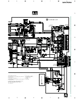
D

C

B

A

The 

>

 mark foun

the importance of

Therefore, when r

identical designat

Symbol indic

No differenti

discrete resis

NOTE :

Symbol indic

No differenti

discrete capa

A-a

A-b

A-a

3

4

Summary of Contents for MEH-P5350

Page 1: ...RAM AND SCHEMATIC DIAGRAM 8 4 PCB CONNECTION DIAGRAM 28 5 ELECTRICAL PARTS LIST 37 6 ADJUSTMENT 41 7 GENERAL INFORMATION 44 7 1 DIAGNOSIS 44 7 1 1 TEST MODE 44 7 1 2 DISASSEMBLY 48 7 1 3 CONNECTOR FUNCTION DESCRIPTION 50 7 2 PARTS 51 7 2 1 IC 51 7 2 2 DISPLAY 57 7 3 OPERATIONAL FLOW CHART 58 8 OPERATIONS AND SPECIFICATIONS 59 This service manual should be used together with the following manual s ...

Page 2: ...nd tools and have been trained to properly and safely repair complex products such as those covered by this manual Improperly performed repairs can adversely affect the safety and reliability of the product and may void the warranty If you are not qualified to perform the repair of this product properly and safely you should not risk trying to do so and refer the repair to a qualified service tech...

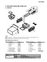
Page 3: ...3 Installation Manual CRD3424 8 4 Polyethylene Bag CEG1116 9 Spring CBH 865 10 Carton CHG4353 11 Contain Box CHL4353 12 Protector CHP2422 13 Protector CHP2421 14 Screw Assy CEA2396 15 Polyethylene Bag CEG 127 16 Screw CRZ50P090FMC 17 Screw TRZ50P080FMC Mark No Description Part No Mark No Description Part No PACKING SECTION PARTS LIST 2 EXPLODED VIEWS AND PARTS LIST 2 1 PACKING 11 8 5 4 6 3 2 7 12 ...

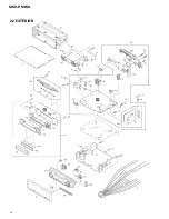
Page 4: ...4 MEH P5350 2 2 EXTERIOR A B ...

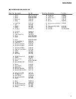
Page 5: ...er Unit CWE1563 27 Holder CNC8815 28 Chassis Unit CXB7119 29 Screw BPZ20P100FMC 30 Button BAND ESC CAC6824 31 Button CAC6825 32 Button SRC CAC6851 33 Button 1 6 CAC7114 34 Button DISP SCRL CAC7012 35 Button FUNC AUDIO CAC7119 36 Button VOLUME CAC7121 37 Keyboard Unit CWM7775 38 LCD LCD701 CAW1686 39 Connector CN701 CKS3580 40 Holder CNC9078 41 Sheet CNM7057 42 Cushion CNM7393 43 Lighting Conductor...

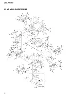
Page 6: ...C D E 6 MEH P5350 2 3 MD MECHANISM MODULE ...

Page 7: ...B CNP5335 44 Gear CNV5616 45 Holder CNV5623 46 Rack CNV5624 47 Rack CNV5625 48 Roller CNV5626 49 Collar CNV5627 50 Damper CNV5629 51 Guide CNV5630 52 Gear CNV5631 53 Gear CNV5633 54 Gear CNV5634 55 Gear CNV5635 56 Gear CNV5636 57 Guide CNV5746 58 Lever CNV5747 59 Lever CNV5748 60 Gear CNV5834 61 Gear CNV5837 62 Gear CNV5838 63 Gear CNV5839 64 Gear CNV5913 65 Composite PCB CNX3127 66 Chassis Unit C...

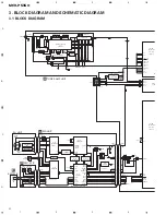
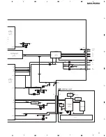
Page 8: ...SET BSI 66 VDSEL 7 TUNPCE CN101 32 Q202 Q991 Q994 M M M LASER DIODE MONITOR DIODE FOCUS ACT LOADING MOTOR DISC SW LOAD SW HOME SW CLMP SW SPDL MOTOR EJCT SW CRG MOTOR TRACKING ACT LD MON F T LO LO SO SO EJECT DISC LOAD HOME CLMP 14 19 1 2 3 10 12 11 9 10 14 13 15 17 3 2 34 33 XOUT AUX2 AUX1 XIN ESW DISC LSW HOME CSW 7 25 15 1 5 3 93 20 AOOTL 28 XRST FEA AUX 96 VREF 86 VDDSW 75 MUTE 95 VDSENSE 44 V...

Page 9: ...LLER IC 601 2 2 PE5213A asens 92 bsens 93 isens asens bsens isens 4 TELIN 27 SYSPWR 21 MUTE 28 KYDT 95 DPDT 96 RESET 11 LCDPW 23 SWVDD 1 ILMPW 20 FL 10 RL 11 POWER AMP IC 301 PAL005A 11 15 22 4 25 21 23 5 3 FL MUTE STBY B REM RL B U TELIN bsens asens ISENS Q951 Q931 Q932 Q301 MUTE Q351 CN351 REAR L CH 4 3 CN701 CN831 ILB LCD701 2 3 X701 8 9 Q352 Q924 Q923 Q921 Q932 B U VCC SYSPW Q811 Q812 Q821 Q82...

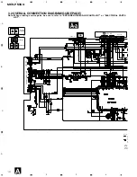
Page 10: ... VIEWS AND PARTS LIST or ELECTRICAL PARTS LIST A a A b A a A a A b A b A b A b A a A a Large size SCH diagram Guide page Detailed page 10 MEH P5350 1 2 3 4 1 2 3 4 D C B A A a MD 1dBs IP BUS 2 2dBs FM 19 5dBs AM 30 0dBs C MD UNIT CN301 FM AM TUNER UNIT IP BUS The the im Theref identic S N d NOTE S N d A ...

Page 11: ...IT B KEYBOARD UNIT CN701 CEK1136 10A FUSE Decimal points for resistor and capacitor fixed values are expressed as 2 2 2R2 0 022 R022 mark found on some component parts indicates mportance of the safety factor of the part efore when replacing be sure to use parts of ical designation Symbol indicates a resistor No differentiation is made between chip resistors and discrete resistors Symbol indicates...

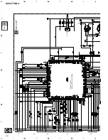
Page 12: ...12 MEH P5350 1 2 3 4 1 2 3 4 D C B A MD 1dBs IP BUS 2 2dBs FM 19 5dBs AM 30 0dBs C MD UNIT CN301 FM AM TUNER UNIT IP BUS A a A a A b 1 2 ...

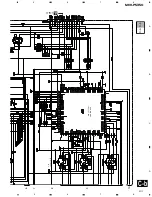
Page 13: ...MEH P5350 5 6 7 8 5 6 7 8 D C B A The mark foun the importance of Therefore when r identical designat Symbol indic No differenti discrete resis NOTE Symbol indic No differenti discrete capa A a A b A a 3 4 ...

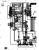
Page 14: ...L151 FM 0 6dBs AM 9 9dBs MD 5 1dBs IP BUS 5 3dBs FM 4 75dBs AM 5 75dBs MD 19 25dBs IP BUS 9 45dBs FM 5 6dBs AM 4 9dBs MD 10 1dBs IP BUS 10 3dBs FM 5 6dBs AM 4 9dBs MD 10 1dBs IP BUS 10 3dBs A TUNER AMP UNIT CEK1136 10A FUSE A a A b A b 1 2 ...

Page 15: ...ues are expressed as 2 2 2R2 0 022 R022 ark found on some component parts indicates tance of the safety factor of the part when replacing be sure to use parts of designation bol indicates a resistor ifferentiation is made between chip resistors and ete resistors bol indicates a capacitor ifferentiation is made between chip capacitors and ete capacitors 600µH A b A a A b 3 4 ...

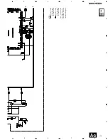
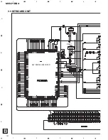
Page 16: ...KEY MICROCOMPUTER RESET 560 R47 2R7K 16 MEH P5350 1 2 3 4 1 2 3 4 D C B A 3 3 KEYBOARD UNIT B ...

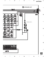
Page 17: ...B LCD BACK LIGTH B A KEYBOARD UNIT CN831 17 MEH P5350 5 6 7 8 5 6 7 8 D C B A ...

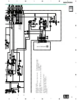
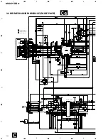
Page 18: ...4 D C B A 3 4 MD MECHANISM MODULE GUIDE PAGE C M1 D FOCUS SERVO LINE TRACKING SERVO LINE CARRIAGE SERVO LINE SPINDLE SERVO LINE F T C S S S C T T F F C C S S T T F F S S C C C C S S F T T F 1 0 4 6 5 fi fl RF AMP 5ch Pow Driver C a ...

Page 19: ...19 MEH P5350 5 6 7 8 5 6 7 8 D C B A CK SELECT A CN991 MD UNIT C MD SYSTEM CONTROLLER 3 5V LEVEL SHIFT S S C C F F T T 2 3 7 8 9 3V Reg DIGITAL SERVO ATRAC ATRAC3 DECODER C C b ...

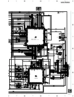
Page 20: ...20 MEH P5350 1 2 3 4 1 2 3 4 D C B A C a FOCUS SERVO LINE TRACKING SERVO LINE CARRIAGE SERVO LINE SPINDLE SERVO LINE F T C S S S C C F T T F 1 RF AMP C a C b 1 2 3 4 5 ...

Page 21: ...21 MEH P5350 5 6 7 8 5 6 7 8 D C B A C a M1 D T T F F C C S S T T F F S S C C C C S S 0 4 6 5 fi fl 5ch Pow Driver C a C b 6 7 8 9 10 ...

Page 22: ...22 MEH P5350 1 2 3 4 1 2 3 4 D C B A MD UNIT C F F T T 2 3 7 8 9 3V Reg DIGITAL SERVO ATRAC ATRAC3 DECODER C a C b 1 2 3 4 5 C b ...

Page 23: ...23 MEH P5350 5 6 7 8 5 6 7 8 D C B A CK SELECT A CN991 MD SYSTEM CONTROLLER 3 5V LEVEL SHIFT C a C b C b 6 7 8 9 10 ...

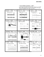
Page 24: ...iv Test mode 32 tracks jump REV 0 5ms div 9 CH1 TEY 0 5V div 0 CH2 TIN 0 2V div Test mode Single jump REV 0 5ms div 9 CH1 TEY 1V div 0 CH2 TIN 0 2V div CH3 CIN 0 5V div Test mode Fine jump REV 5ms div 8 CH1 FEY 0 2V div 4 CH2 FIN 0 2V div Normal mode Play 5ms div 4 CH1 FIN 0 1V div CH2 SIN 0 5V div Normal mode Play 0 5s div 4 CH1 FIN 0 1V div CH2 SIN 0 5V div Normal mode Play Recordable MD 0 5s di...

Page 25: ... MD 0 2s div 50ms div 1 Use the AGND pin for grounding GND 2 Use the GND pin for grounding GND Due to dispersion in electrical and mechanical characteristics of the MD MECH module observed waveforms for TEY TIN FEY and FIN signals might be a little different from those shown below 50ms div 500ms div 50ms div CH1 ROUT 1V div CH2 LOUT 1V div Normal mode Play 1kHz 0dB 0 5ms div 8 CH1 FEY 0 2V div 4 C...

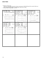
Page 26: ...the probe of an oscilloscope apart from each other 2 Use the GND pin for grounding GND 2 CH1 MLOAD 5V div CH2 MEJCT 5V div CH3 EJCT 5V div CH4 LOM 5V div Normal mode Eject 0 2s div 2 CH1 MLOAD 5V div CH2 CIN 1V div fi CH3 HOME 5V div fl CH4 DISC 5V div Normal mode Load 0 2s div 2 CH1 MLOAD 5V div CH2 CIN 1V div fi CH3 HOME 5V div fl CH4 DISC 5V div Normal mode Load Recordable MD 0 2s div 2 CH1 ADFG 2V...

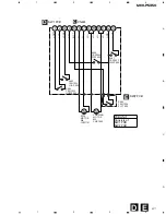
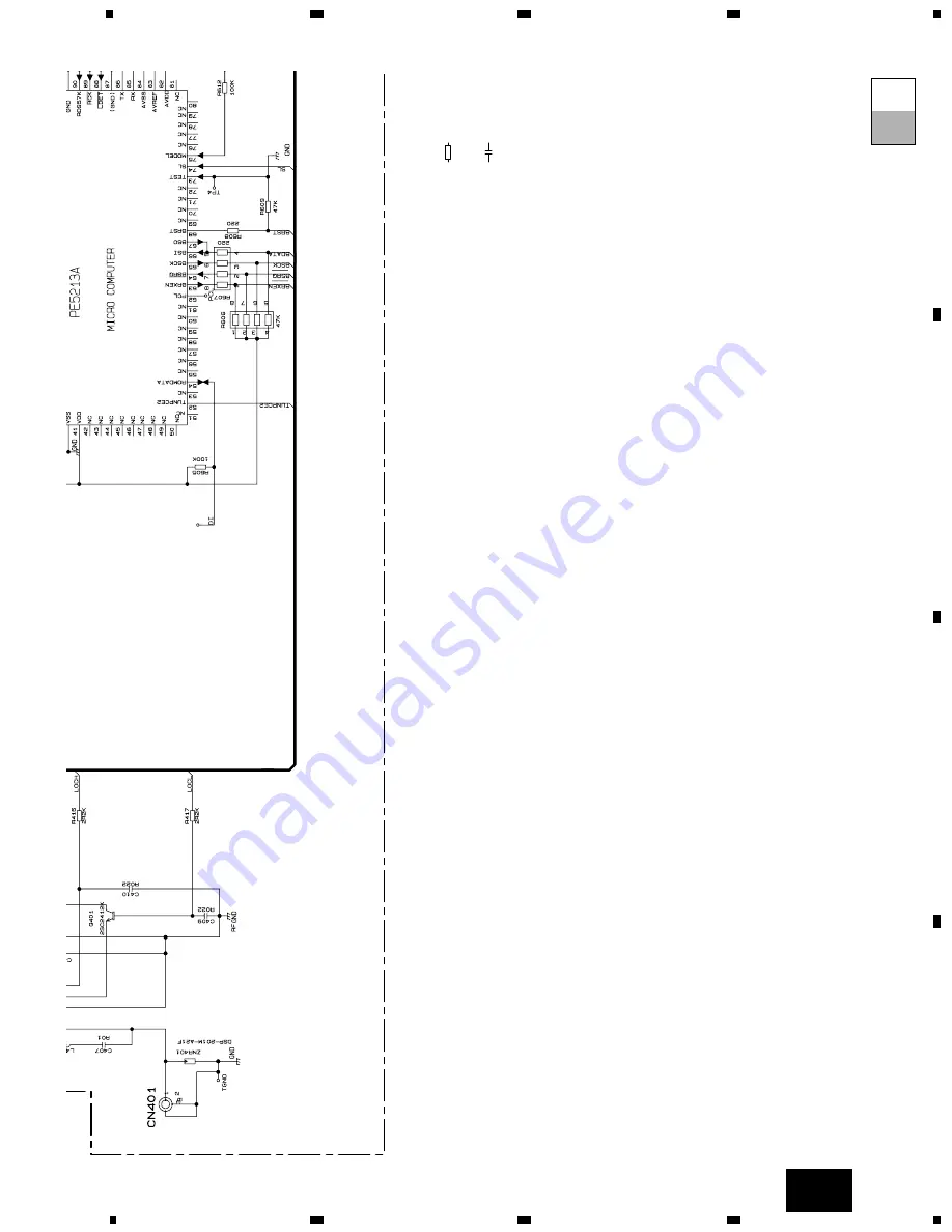
Page 27: ... 6 SO 7 8 SO LO 9 LO 10 11 LO LO 12 GND 13 CLMP M M S402 CSN1052 HOME SW S405 CSN1052 LOAD SW S404 CSN1042 DISC SW S401 CSN1055 CLMP SW S403 CSN1053 EJCT SW LOADING MOTOR M2 CXB7603 SPDL MOTOR M3 CXM1181 E D E SW2 PCB D SW1 PCB PCB UNIT Consists of SW1 PCB SW2 PCB C CN401 ...

Page 28: ...MS 1 The parts mounted on this PCB include all necessary parts for several destination For further information for respective destinations be sure to check with the schematic dia gram 2 Viewpoint of PCB diagrams A A Capacitor Connector P C Board Chip Part SIDE A SIDE B TUNER AMP UNIT B CN701 CORD ASSY ...

Page 29: ...29 MEH P5350 5 6 7 8 5 6 7 8 D C B A A SIDE A IC Q FRONT IP BUS REAR OUT ANTENNA FM AM TUNER UNIT C CN301 ...

Page 30: ...30 MEH P5350 1 2 3 4 1 2 3 4 D C B A A A TUNER AMP UNIT ...

Page 31: ...31 MEH P5350 5 6 7 8 5 6 7 8 D C B A A SIDE B ...

Page 32: ...32 MEH P5350 1 2 3 4 1 2 3 4 D C B A 4 2 KEYBOARD UNIT DISPLAY EQ SFEQ SRC SRC 1 2 3 4 5 6 CLOCK BAND EJECT FUNCTION AUDIO B B SIDE A KEYBOARD UNIT ...

Page 33: ...33 MEH P5350 1 2 3 4 1 2 3 4 D C B A A CN831 B B SIDE B KEYBOARD UNIT ...

Page 34: ...IC Q E E 1 CN991 A 34 MEH P5350 1 2 3 4 1 2 3 4 D C B A 4 3 MD MECHANISM MODULE MD UNIT C C PU UNIT SIDE A ...

Page 35: ...IC Q D 35 MEH P5350 D C B A 1 2 3 4 1 2 3 4 C MD UNIT C SIDE B ...

Page 36: ...36 MEH P5350 1 2 3 4 1 2 3 4 D C B A S403 EJCT SW S405 LOAD SW S404 DISC SW SW2 PCB SW1 PCB M2 LOADING MOTOR M3 SPINDLE MOTOR E D D CN401 S401 CLMP SW E E S402 HOME SW C D ...

Page 37: ... B3 D 931 Diode HZS7L C3 D 932 Diode HZS7L A1 D 951 Diode DAN202U D 971 Diode MPG06G 6415G50 D 972 Diode MPG06G 6415G50 D 991 Diode HZS9L B1 D 992 Diode HZS6L B2 D 993 Diode RB160L 40 ZNR 401 DSP 201M A21F L 101 Ferri Inductor LAU2R2K L 401 Ferri Inductor LAU2R2K L 402 Ferri Inductor LAU1R0M L 403 Ferri Inductor LAU4R7K L 601 Ferri Inductor LAU2R2K L 651 Inductor LAU100K L 801 Ferri Inductor LAU2R...

Page 38: ...04 CEJQ1R0M50 C 105 CEJQ1R0M50 C 106 CEJQ1R0M50 C 151 CKSRYB104K16 C 152 CEJQ470M10 C 153 CEJQNP4R7M16 C 154 CEJQNP4R7M16 C 157 CEJQNP4R7M16 C 158 CEJQNP4R7M16 C 161 CEJQNP4R7M16 C 162 CEJQNP4R7M16 C 165 CEJQ100M16 C 301 CFTNA224J50 C 302 CFTNA224J50 C 303 CFTNA224J50 C 304 CFTNA224J50 C 305 CEJQ330M10 C 306 CFTNA105J50 C 307 CEJQ100M16 C 308 CKSRYB104K16 C 309 4700µF 16V CCH1362 C 351 CEJQ4R7M35 ...

Page 39: ...16SE1002D R 308 RS1 16S104J R 309 RAB4C104J R 310 RS1 16S104J R 311 RS1 16S473J R 312 RAB4C681J R 313 RAB4C681J R 314 RAB4C104J R 315 RS1 16S393J R 316 RS1 16S104J R 317 RS1 16S683J R 318 RS1 16S0R0J R 319 RS1 16S0R0J R 401 RS1 16S221J R 402 RS1 16S222J R 403 RS1 16S333J R 404 RS1 16S333J R 405 RS1 16S222J R 406 RS1 16S0R0J R 407 RS1 16S121J R 408 RS1 16S332J R 409 RS1 16S183J R 410 RS1 16S0R0J R ...

Page 40: ...SSW440 9159 D 703 LED SML210PT D 704 LED SML210PT D 705 LED SML210PT D 706 LED SML210PT D 707 LED SML210PT D 708 LED SML210PT D 709 LED SML210PT D 710 LED SML210PT X 701 Radiator CSS1559 IL 701 Lamp 40mA 14V CEL1687 IL 702 Lamp 40mA 14V CEL1687 LCD 701 LCD CAW1686 RESISTORS R 701 RS1 16S222J R 702 RS1 16S222J R 703 RS1 16S2R2J R 704 RS1 16S121J R 706 RS1 16S5600D R 707 RS1 16S2701D R 708 RS1 16S82...

Page 41: ...it diagram Disc discrimination can be confirmed by the following indications appearing under the above octonary digits the TEST MD mode after completing floating of the disc under the TEST mode In case of high refection 02200000 In case of low refection 01100000 The second and third digits counting from the Left hand side will become 2 or 1 Unless disc discrimination is made properly accurate auto...

Page 42: ... 02200 00 Disc discrimination High reflection 2 02210 00 Offset adjustment 1 12210 00 LD on 1 22210 00 Focus close When the pickup has been replaced Re adjust when the grating deviation exceeds 30 deg Refer to the drawing indicated below and grating waveform 1 Slightly loosen the screws 2 and 3 for the spindle motor do not touch the screw 1 and inserting a minus screwdriver head into the groove tu...

Page 43: ...43 MEH P5350 Grating waveform 45 0 75 60 30 90 Ech Xch 50mV div AC Fch Ych 50mV div AC ...

Page 44: ...nt starts Indication XXXcXXs Cluster Sector Positions of the cluster and the Disc Starting and ending addresses are approximate ones PreDisc FFE0 inner periphery 0000 0900 outer periphery RecDisc 0032 inner periphery 0900 outer periphery Address changing method 1 After the tracing movement ends select the desired address 0003 0032 00b4 0500 0700 using the 6 key 2 Disc to execute or 1 After the tra...

Page 45: ...ure Imperfect contact between the IC and the microcomputer or IC failure 17 IV Adjustment_NG IV adjustment failure Imperfect contact between the IC and the microcomputer or IC failure 17 EF B Adjustment_NG EF B adjustment failure Imperfect contact between the IC and the microcomputer or IC failure 20 TOC_TIMEOUT TOCREAD_timeout Time is over after various retries 21 UTOC_TIMEOUT UTOCREAD_timeout Ti...

Page 46: ...ect Spindle stop Monitor output is changed over with the toggle Determination with DISC Normal track search Normal track search P UP address making sound address RAM remaining capacity F T ERR times NEW CRG value are rotated with the toggle ERR count value reset After the 1 minute display the original screen appears Occurrence sequence and NG and ERR codes It returns to IDLE ERR times out of focus...

Page 47: ...is turned on by force The four EQs are rotated with the toggle Returns to the upper level Motion at the home position The mode of disc is changed irrespectively of the state of the mechanical switch The display at the above treble digit is changed over according to the mode is determined with S curve measurement Comes off with pre pushing Befor FCLOSE 1XXX After FCLOSE 2XXX After the adjustment en...

Page 48: ...and then remove the Tuner Amp Unit Removing the Case not shown 1 Remove the Case Removing the MD Mechanism Module Fig 1 Remove the four screws Disconnect the connector and then remove the MD Mechanism Module Removing the Grille Assy Fig 1 Disconnect the three stoppers and then remove the Grille Assy Fig 1 Fig 2 Tuner Amp Unit MD Mechanism Module Grille Assy ...

Page 49: ...r in section A then remove the connector 2 Remove the two screws then erect the board in the direction indicated by the white arrow head 3 Remove the two screws and two springs 4 Drive out the PU Unit through the direction indicated by the white arrow head ...

Page 50: ...T 8 ASENB 9 BUS R INPUT 10 BUS R INPUT 11 BUS L INPUT 11 10 9 8 7 6 5 4 3 2 1 REAR OUTPUT ANTENNA JACK 1 RR 2 FR 3 RR 4 FR 5 RL 6 FL 7 RL 8 FL 9 NC 10 TEL 11 ILM 12 B REM 13 ACC 14 NC 15 GND 16 B UP FUSE 10A 1 2 10 16 15 7 1 3 CONNECTOR FUNCTION DESCRIPTION L R ...

Page 51: ...tput 27 TELIN I Telephone mute input 28 MUTE O System mute output 29 30 NC Not used 31 LOCL O LOCL output 32 LOCH O LOCH output 33 VCK O Clock output for electronic volume 34 VST O Strobe pulse output for electronic volume 35 VDT O Data output for electronic volume 36 emute O E VOL mute output 37 A ANT O Not used 38 SD I Station detector input 39 ST I FM stereo input 40 VSS GND 41 VDD Power supply...

Page 52: ...0 31 50 51 80 81 100 1 IC s marked by are MOS type Be careful in handling them because they are very liable to be damaged by electrostatic induction 1 TAB 2 P GND2 3 OUT2 4 STBY 5 OUT2 6 VCC 7 OUT1 8 P GND1 9 OUT1 10 SVR 11 IN1 12 IN2 13 S GND 14 IN4 15 IN3 16 AC GND 17 OUT3 18 P GND3 19 OUT3 20 VCC 21 OUT4 22 MUTE 23 OUT4 24 P GND4 SWITCH 25 Offset Detection Offset Detection Offset Detection Offs...

Page 53: ...used 95 98 V4 1 LCD drive power supply 99 100 C1 C0 Not used PD2068A 30 31 50 51 80 81 100 1 Format Meaning C C MOS L LCD C output DGND CLK Vref NC MUTE STB DATA IN4 _R IN4 _R IN3_R IN1_R IN2_R Vcc IN1_L IN2_L IN3_L IN4 _L IN4 _L 12 11 10 9 8 7 6 5 4 3 2 1 20 19 18 17 16 15 14 13 30 29 28 27 26 25 24 23 22 21 40 39 38 37 36 35 34 33 32 31 44 43 42 41 Tone_out_RL SV_in_RL SV_in_FL Tone_out_FL Front...

Page 54: ...05 106 107 108 109 110 111 112 113 114 115 116 117 118 119 120 SE TE AUX2 DCHG APC DDIN DDOUT ASYO ASYI AVDI BIAS RFI AVSI PCO FILI FILO CLTV VDC3 VSC3 FS4 SRDR SFDR SPRD SPFD FGIN TEST1 TEST2 TEST3 MTFLGR TRK FOK FKS 60 59 58 57 56 55 54 53 52 51 50 49 48 47 46 45 44 43 42 41 40 39 38 37 36 35 34 33 32 31 D1 GFS DVSS DVDD XWE XRAS A09 XCAS XOE VSIO1 A11 A08 A07 A06 A05 A04 A10 A00 A01 A02 A03 VDI...

Page 55: ... O C P BUS clock input output 36 NC Open 37 bsrq O C P BUS serial pole request output 38 BRXEN I O C Receivable I O 39 42 NC Open 43 LDCNT O C Laser diode ON OFF 44 VDON O C Power ON OFF 45 59 NC Open 60 VCC2 5V 61 CK I Clock signals 62 VSS2 GND 63 74 NC Open 75 MUTE O C Comprehensive mute output 76 CONT O C Servo driver power control 77 MDEJECT O C Loading motor control output 78 MDLOAD O C Loadi...

Page 56: ...he VDD at 47kΩ 16 CE1 I chip enable 1 AF RF chip enable Active at High To be grounded at 47kΩ 17 NC Not used 18 LDET O lock detector Active at Low To be pulled up to the VDD at 47kΩ 19 CREQ I current request Active at Low To be grounded at 47kΩ 20 NC Not used 21 COMP O composite signal FM composite signal output r out 100Ω 22 VCC power supply Analog section power supply pin D C 8 4V 0 3V 23 LOCH I...

Page 57: ...EG SEG SEG15 SEG SEG SEG16 SEG SEG SEG17 SEG SEG SEG18 SEG SEG SEG19 SEG SEG SEG20 SEG SEG SEG21 SEG SEG SEG25 SEG SEG SEG26 SEG SEG SEG24 SEG SEG22 SEG23 SEG SEG SEG SEG SEG SEG SEG SEG SEG SEG SEG27 SEG28 SEG29 SEG30 SEG31 SEG32 SEG33 SEG34 SEG35 SEG36 SEG37 SEG38 SEG39 SEG40 SEG41 SEG42 SEG43 SEG44 SEG45 SEG46 SEG47 SEG48 SEG49 SEG50 SEG51B SEG52B SEG53B SEG54B SEG55B SEG SEG SEG 9 SEG 9 SEG 9 ...

Page 58: ...Completes power on operation After that proceed to each source operation SYSPW H 21pin Starts communication with Grille microcomputer Source ON 300ms 300ms In case of the above signal the communication with Grille microcomputer may fail If the time interval is not 300msec the oscillator may be defective IPPW H 24pin ASNBO H 25pin BRST H 68pin ...

Page 59: ... when using buttons on the head unit ATT button This lets you quickly lower volume level by about 90 Press once more to return to the original volume level FUNCTION button SOURCE OFF button BAND button button 5 buttons 2 3 buttons AUDIO button PGM button EQ button buttons MD Loading Slot AUDIO button SFEQ button 5 2 3 buttons BAND button Buttons 1 6 FUNCTION button DISPLAY button CLOCK button EJEC...

Page 60: ...gramed by each source A press of PGM button activates the functions in the following chart Source Function name Tuner Best Stations Memory OFF Best Stations Memory ON Hold for 2 seconds Built in MD player Pause CD player one disc only Pause Multi CD player Pause TV Best Station Sequential Memory OFF Best Station Sequential Memory ON Hold for 2 seconds Note For the details of TV and CD player one d...

Page 61: ...F 2 Raise or lower the volume 3 Turn the source OFF Hold for 1 second Each press changes the Source Basic Operation Basic Operation of Tuner Reset the AM tuning step from 9 kHz the factory preset step to 10 kHz when using the tuner in North Central or South America Manual and Seek Tuning You can select the tuning method by changing the length of time you press the 2 3 button Manual Tuning step by ...

Page 62: ...an MD after confirming the MD shutter is closed Do not insert anything other than a MD into the MD Loading Slot Basic Operation Basic Operation of Multi CD Player This product can control a Multi CD player sold separately Play Time Indicator Track Number Indicator Disc Number Indicator Disc Number Search for 6 Disc 12 Disc types You can select discs directly with the 1 to 6 buttons Just press the ...

Page 63: ...d To electric terminal controlled by ignition switch 12 V DC ON OFF 10 Orange white To lighting switch terminal 24 Rear speaker or Subwoofer 24 Rear speaker or Subwoofer 17 Front speaker 24 Rear speaker or Subwoofer 24 Rear speaker or Subwoofer 14 Power amp sold separately 31 12 Fuse 6 IP BUS cable 4 IP BUS input Blue 1 This Product 3 Antenna jack 2 Rear or Subwoofer output 5 Multi CD player sold ...

Page 64: ...10 kHz Mid 10 dB 100 Hz 6 5 dB 10 kHz High 11 dB 100 Hz 11 dB 10 kHz volume 30 dB Tone controls Bass Frequency 40 63 100 160 Hz Level 12 dB Treble Frequency 2 5k 4k 6 3k 10k Hz Level 12 dB Subwoofer output Frequency 50 80 125 Hz Slope 12 dB oct Gain 12 dB MD player System Mini disc digital audio system Usable discs Mini disc Signal format Sampling frequency 44 1 kHz Number of quantization bits 16 ...

Reviews: