background image

MJ-L5, SP-L5

35

A

B

C

D

1

2

3

4

1

2

3

4

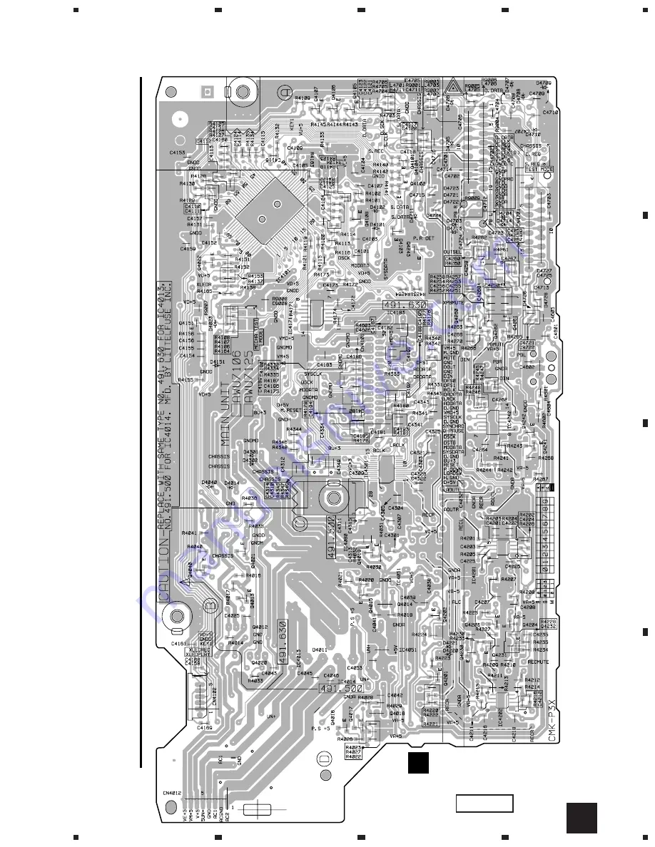
MD MAIN UNIT

C

(ANP7249-B)

Q4015

|     

Q4017

Q4101

Q4104

Q4102

Q4243

Q4260

|     

Q4262

Q4242

Q4241

Q4108
Q4103

Q4022

Q4151

IC4250

IC4101

IC4171

IC4240

IC4301

Q4019

Q4021

Q4040

Q4013

Q4015

Q4201

IC4201

IC4202

Q4016
Q4017

Q4202

|     

Q4204
Q4230

|     

Q4232

C

SIDE B

Summary of Contents for MJ-L5

Page 1: ... 75 7 3 DISASSEMBLY 77 7 4 BLOCK DIAGRAM 82 8 PANEL FACILITIES AND SPECIFICATIONS 84 T IZY AUG 1998 Printed in Japan SP L5 THIS MANUAL IS APPLICABLE TO THE FOLLOWING MODEL S AND TYPE S SURROUND PROCESSOR This products is a system component It combined the following components MINIDISC RECORDER MJ L5 SURROUND PROCESSOR SP L5 This products is a system component For the system composition refer to th...

Page 2: ...vel OFF high level position IC104 get the LOAD signal and hand the laser LDON signal to No 9 terminal LDON of the Laser pickup assy Then a laser diode can be lighted exept when the level of signal LOAD is low Additional Laser Caution LABEL CHECK for MJ L5 MYXK and NVXK only 1 SAFETY INFORMATION This service manual is intended for qualified service technicians it is not meant for the casual do it y...

Page 3: ...4 Sheet 750 600 0 5 Z23 007 5 Sub Packing See Contrast table 2 6 Power Cord See Contrast table 2 7 Optical Fiber Cable RKX1031 8 Power Cord See Contrast table 2 9 Fuse T5A See Contrast table 2 10 Polyethylene Bag Z21 038 0 03 230 340 11 Operating Instructions See Contrast table 2 English French German Italian 12 Operating Instructions See Contrast table 2 English 13 Operating Instructions See Cont...

Page 4: ...L5 SP L5 Refer to 2 1 3 TOP PANEL ASSY 25 15 14 14 13 13 13 11 10 8 9 25 16 13 12 25 21 25 24 24 27 6 25 5 2 26 26 26 17 18 3 4 1 25 16 19 25 20 16 7 Refer to 2 1 4 MD MECHANISM ASSY 23 22 26 2 1 2 EXTERIOR ...

Page 5: ...oat Screw RBA1133 15 MD Shield ANG7192 Mark No Description Part No 16 Angle ANG7189 17 Rear Panel See Contrast table 2 18 Cord With Plug J1 ADE7026 19 Shield Barrier AEC7164 20 Rivet VEC1178 21 Earth Plate ANG7168 22 Bonnet AMA7007 NSP 23 Caution Label See Contrast table 2 24 Screw BPZ30P060FZK 25 Screw BBZ30P060FMC 26 Screw VPZ30P080FZK 27 Screw BBZ40P060FMC 2 CONTRAST TABLE MJ L5 MYXK and MJ L5 ...

Page 6: ...PARTS LIST Mark No Description Part No 1 MD KEYR Unit AWU7108 2 MD KEYL Unit AWU7109 3 Top Panel AMB7515 4 Sub Panel MD AAP7049 5 MD Flap AAN7186 6 MD Spring ABH7154 7 Flap Plate AAT7003 8 Button X Assy AWL7034 9 Sub Panel AAP7048 NSP 10 Top Plate ANK7042 11 Rivet VEC1178 12 Screw VPZ30P080FZK ...

Page 7: ...ASSY 49 48 40 22 42 38 43 40 33 44 31 28 32 34 40 11 5 10 17 7 6 4 9 37 19 21 20 18 37 16 26 15 13 14 37 12 53 52 51 A E E F F G G H A B B C C D D 37 8 40 24 25 39 27 41 35 36 29 39 46 23 30 45 2 3 50 47 37 CN103 CN101 CN102 CN105 1 H ...

Page 8: ...crew RBA1129 23 Spindle Spring RBH1460 24 Lifter SP RBH1462 25 Screw Guide RBK1072 26 S H Spring RBK1073 27 Guide Shaft RLA1310 28 Lead Screw RLA1311 29 Shield Case RNE1950 30 Reference Plate RNK2306 31 S Holder RNK2307 32 Worm Wheel RNK2309 33 Hook RNK2310 34 Head Lifter RNK2311 35 MD Head RPB1062 36 MD Pickup RWY1018 37 Screw IPZ20P080FMC 38 Screw JFZ17P020FZK 39 Screw JGZ14P020FMC 40 Screw JGZ1...

Page 9: ...s See Contrast table 2 English French German Italian Dutch Swedish Spanish Portuguese 12 Operating Instructions See Contrast table 2 English 13 Battery Cover AZA7050 NSP 14 Warranty Card ARY7022 NSP 15 Serial Paper RRW 168 NSP 16 Dry Cell Battery R03 AAA PEM1004 2 CONTRAST TABLE SP L5 MYXK and SP L5 NVXK are constructed the same except for the following Mark No Symbol and Description Part No Remar...

Page 10: ...10 MJ L5 SP L5 Refer to 2 2 3 TOP PANEL ASSY 17 16 21 21 20 10 8 9 19 22 20 20 23 7 15 24 13 24 24 14 24 4 5 3 2 21 12 6 21 21 21 11 1 18 24 2 2 2 EXTERIOR ...

Page 11: ...m Plate ANF7010 11 Angle ANG7189 12 Cord Clamper RNH 184 13 Rear Panel See Contrast table 2 14 Rear Case AMR7207 15 Cord With Plug J ADE7026 16 Top Barrier AEC7151 17 Rivet VEC1178 18 Bonnet AMA7007 19 Name Label ARW7043 20 Screw BPZ30P060FZK 21 Screw BBZ30P060FMC 22 Screw BBZ40P060FMC 23 Screw BBZ30P140FMC 24 Screw VPZ30P080FZK 2 CONTRAST TABLE SP L5 MYXK and SP L5 NVXK are constructed the same e...

Page 12: ...ST Mark No Description Part No 1 PRO KEYR Unit AWU7104 2 PRO KEYL Unit AWU7105 3 PRO IND Unit AWU7145 4 Top Panel AMB7516 5 Sub Panel PR AAP7050 6 Lens D AAX7640 7 Illumination Filter VEC1950 8 Illumination Holder VNK4098 9 Button X Assy AWL7035 NSP 10 Top Plate ANK7048 11 Screw VPZ30P080FZK 12 Rivet VEC1178 ...

Page 13: ...13 MJ L5 SP L5 ...

Page 14: ...MINIDISC RECORDER MJ L5 3 1 1 OVERALL CONNECTION DIAGRAM MD MAIN UNIT AWU7106 MD TRANS UNIT AWU7107 D MD REG2 UNIT AWU7155 MD REG1 UNIT AWU7154 E F MD KEYR UNIT AWU7108 G MD KEYL UNIT AWU7109 H C C 1 2 C 2 2 AC POWER CORD MYXK ADG7010 AC220 230V NVXK ADG7009 AC230V ...

Page 15: ...L5 STEREO CD RECEIVER XC L5 or SURROUND PROCESSOR SP L5 INTERFACE IC4240 BU4066BCF JA4601 GP1F32R IC4171 TC74HCT08AF REC AMP IC4202 NJM4558MD BUFFER ALC IC4201 NJM4558MD BUFFER IC4250 NJM4558MD AD DA CONVERTER OUTPUT SEL IC4301 AK4520A Q4203 Note When ordering service parts be sure to refer to EXPLODED VIEWS and PARTS LIST or PCB PARTS LIST ...

Page 16: ... MD CORE MAIN UNIT RWZ4326 A MD CORE SW UNIT RWZ4272 B LOADING MOTOR SLED MOTOR SPINDLE MOTOR YELLOW BLACK ORANGE BLUE BLACK RED INSIDE SW A DISC PROTECT B DISC MEDIA DETECT PICKUP 1 2 3 10 11 8 9 A B 3 1 2 MD CORE MAIN and MD CORE SW UNITS ...

Page 17: ...C D 5 6 7 8 5 6 7 8 INSIDE C CN4101 1 2 YB 0 01 R291 R293 47k PLAYBACK SIGNAL REC SIGNAL OUTPUT DIGITAL AUDIO SIGNAL INPUT DIGITAL AUDIO SIGNAL RF SIGNAL SIGNAL ROUTE 6 5 7 4 A A 1 are waveform numbers on pages 24 and 25 ...

Page 18: ...MJ L5 SP L5 18 A B C D 1 2 3 4 1 2 3 4 C 1 2 C 1 2 MD MAIN UNIT 1 2 AWU7106 C 2 2 A CN104 4 9 4 9 4 9 4 9 3 2 5 D D D D D D D D D 5 4 4 4 1 3 3 1 3 MD MAIN 1 2 MD TRANS MD REG1 and MD REG2 UNITS ...

Page 19: ...TELFUSE INC FOR IC4013 AEK7006 CAUTION FOR CONTINUED PROTECTION AGAINST RISK OF FIRE REPLACE WITH SAME TYPE NO 491 500 MFD BY LITTELFUSE INC FOR IC4014 AEK7005 CAUTION FOR CONTINUED PROTECTION AGAINST RISK OF FIRE REPLACE WITH SAME TYPE NO 491001 MFD BY LITTELFUSE INC FOR IC4052 AEK7009 DECK CT L5 STEREO CD RECEIVER XC L5 or SURROUND PROCESSOR SP L5 4 9 4 4 4 9 4 9 5 5 13 3 PLAYBACK SIGNAL ROUTE R...

Page 20: ...MJ L5 SP L5 20 A B C D 1 2 3 4 1 2 3 4 C 2 2 MD MAIN UNIT 2 2 AWU7106 MD KEYL UNIT AWU7109 H MD KEYR UNIT AWU7108 G C 2 2 G H 3 1 4 MD MAIN 2 2 MD KEYR and MD KEYL UNITS ...

Page 21: ...MJ L5 SP L5 21 A B C D 5 6 7 8 5 6 7 8 C 1 2 C 1 2 C 2 2 ...

Page 22: ... 0V 3 18V 0 02V 3 19V 3 2V 0V 0 05V 3 18V 3 19V 0 51V 0 4V 0 3V 0 55V 9 8 7 6 5 4 3 2 1 30 29 28 27 26 25 24 23 22 21 20 19 18 17 16 15 14 13 12 11 10 49 48 47 46 45 44 43 42 41 40 39 38 37 36 35 34 33 32 31 PIN NO VOLTAGE 50 IC104 0 54V 0 6V 0 6V 0 6V 0V 0V 0V 0V 3 2V 0V 0V 3 2V 0V 0V 3 2V 0V 0V 0V 0V 0V 0V 3 1V 3 2V 0V 0V 3 2V 0V 0V 0V 3 2V 0V 3 19V 0V 3 19V 0V 3 18V 3 2V 0V 1 03V 1 6V 0 56V 1 4...

Page 23: ...9V 4 99V 1 61V 1 62V 2 46V 2 51V 0V 0V 2 54V 2 45V 1 62V 1 62V 1 61V 3 17V 0V 1 61V 1 61V 1 61V 1 61V 1 36V 1 36V 1 61V 1 61V 1 63V 2 41V 2 55V 2 47V 2 48V 0V 0V 2 79V 2 18V 0V 1 69V 5 0V 4 99V 1 67V 1 69V 1 69V 9 8 7 6 5 4 3 2 1 30 29 28 27 26 25 24 23 22 21 20 19 18 17 16 15 14 13 12 11 10 42 41 40 39 38 37 36 35 34 33 32 31 VOLTAGE IC106 PIN NO 1 66V 1 62V 1 62V 0V 1 67V 1 67V 1 67V 3 19V 8 7 6...

Page 24: ...1 or MMD 110 7 IC102 pin54 TES01 MODE STOP GND DC2V div 10 µSec div 4 GND DC1V div 0 2 µSec div IC102 pin50 EFMO MODE REC DISC GGF1328 MMD 212 5 IC102 pin75 FE MON MODE PLAY DISC TGTS1 or MMD 110 GND DC100mV div 2mSec div 39 kΩ 820pF FE MON Note The encircled numbers denote measuring point in the schematic diagram and the PCB connection diagram Measurement Method Measurement Method REFO MD Mechani...

Page 25: ... 25 11 GND DC1V div 1mSec div CN105 pin1 LOAD MODE EJECT 8 GND DC500mV div 2mSec div CN103 pin1 SLD MODE PLAY 9 CN103 pin4 SP MODE PLAY GND DC500mV div 5mSec div 10 CN105 pin1 LOAD MODE STOP GND DC1V div 1mSec div ...

Page 26: ... DIAGRAM PRO KEYL UNIT AWU7105 N PRO AMP UNIT AWU7102 K PRO TRANS UNIT AWU7103 J PRO KEYR UNIT AWU7104 L PRO IND UNIT AWU7145 M IC3401 POWER AMP 10dB AMP FUNC1 DOLBY BUFFER1 REAR CENTER VOL IC3201 IC3551 IC3571 IC3701 IC3001 C S C L R S AC POWER CORD MYXK ADG7010 AC220 230V NVXK ADG7009 AC230V ...

Page 27: ...MJ L5 SP L5 27 A B C D 5 6 7 8 5 6 7 8 1 2 2 2 PRO MAIN UNIT AWU7101 I PRO AUX UNIT AWU7146 O I I FUNC2 IC3501 BUFFER2 IC3531 STEREO CD RECEIVER XC L5 DECK CT L5 or MINIDISC RECORDER MJ L5 SPEAKER ...

Page 28: ... IC22 MFD BY LITTELFUSE INK CAUTION FOR CONTINUED PROTECTION AGAINST RISK OF FIRE REPLACE ONLY WITH SAME TYPE NO 49103 5 MFD BY LITTELFUSE INC FOR IC3 AND IC4 CAUTION FOR CONTINUED PROTECTION AGAINST RISK OF FIRE REPLACE ONLY WITH SAME TYPE NO 491 315 MFD BY LITTELFUSE INC FOR IC1 C2 0 01 250 0 01 250 H1 H2 AKR1003 IC11 AEK7009 1A 125V IC12 AEK7009 1A 125V AEK7021 7A 125V AEK7021 7A 125V AEK7017 3...

Page 29: ... 8 1 2 I K 1 2 PRO MAIN UNIT AWU7101 PRO AMP UNIT AWU7102 2 2 C CH AUDIO SIGNAL ROUTE S CH AUDIO SIGNAL ROUTE K I I AKE7042 L3461 L3462 ATH 059 R3461 100 R3462 100 R3617 R3618 ACN7032 IC3201 1 2 IC3201 2 2 SPEAKER 26 5 26 5 25 3 POWER AMP ...

Page 30: ...PRO IND PRO KEYL and PRO AUX UNITS PRO KEYR UNIT AWU7104 L PRO KEYL UNIT AWU7105 N PRO IND UNIT AWU7145 M 1 2 I 1 2 I S5901 S5902 RSG1031 S5921 S5922 RSG1030 IC5501 PDC046A AC PULSE 5 9 3 PRO KEYR UNIT S5901 SFC ON OFF S5902 SFC MODE PRO KEYL UNIT S5921 DELAY TIME S5922 DOLBY MODE ...

Page 31: ...H AUDIO SIGNAL ROUTE S CH AUDIO SIGNAL ROUTE O 1 2 I I REC REC REC VCR REC REC VCR DVD DVD DVD DVD VCR DVD VCR DVD VCR VCR REC PB PB PB PB REC REC PB REC REC IC3571 1 2 NJM4558MD IC3531 1 2 NJM4558MD IC3531 2 2 NJM4558MD IC3571 2 2 NJM4558MD D5201 D5204 UDZ15B STEREO CD RECEIVER XC L5 DECK CT L5 or MINIDISC RECORDER MJ L5 ...

Page 32: ...on for respective destinations be sure to check with the schematic diagram 4 View point of PCB diagrams Symbol In PCB Diagrams Symbol In Schematic Diagrams Part Name B C E D D G G S S B C E B C E D G S B C E B C E B C E Transistor Transistor with resistor Field effect transistor Resistor array 3 terminal regulator Capacitor Connector P C Board Chip Part SIDE A SIDE B B SIDE A SIDE B 4 PCB CONNECTI...

Page 33: ...ICKUP ASSY IC101 IC112 IC108 IC113 IC109 IC110 IC116 Q103 Q104 IC106 IC102 IC103 IC104 IC114 Q101 Q102 RNP1721 B RNP1721 B CN701 B CN4101 C MD CORE MAIN UNIT A 1 2 6 7 5 9 8 4 10 11 3 4 1 2 MD CORE MAIN UNIT 1 are waveform numbers on pages 24 and 25 A SIDE A SIDE B ...

Page 34: ...4 1 2 3 4 CN4011 D J4901 G CN104 A MD MAIN UNIT C ANP7249 B IC4183 IC4022 IC4080 IC4025 IC4024 IC4051 IC4013 IC4014 Q4018 Q4020 Q4012 Q4014 STEREO CD RECEIVER XC L5 or SURROUND PROCESSOR SP L5 DECK CT L5 C 4 1 3 MD MAIN UNIT SIDE A ...

Page 35: ... MD MAIN UNIT C ANP7249 B Q4015 Q4017 Q4101 Q4104 Q4102 Q4243 Q4260 Q4262 Q4242 Q4241 Q4108 Q4103 Q4022 Q4151 IC4250 IC4101 IC4171 IC4240 IC4301 Q4019 Q4021 Q4040 Q4013 Q4015 Q4201 IC4201 IC4202 Q4016 Q4017 Q4202 Q4204 Q4230 Q4232 C SIDE B ...

Page 36: ... 2 3 4 CN4012 C MD TRANS UNIT D MD KEYL UNIT H MD REG2 UNIT F MD REG1 UNIT E MD KEYR UNIT G AC POWER CORD IC4012 IC4052 IC4011 IC4016 IC4015 CN4102 C ANP7249 B 4 1 4 MD TRANS MD REG1 MD REG2 MD KEYR and MD KEYL UNITS D E F G H SIDE A ...

Page 37: ...MJ L5 SP L5 37 A B C D 1 2 3 4 1 2 3 4 MD TRANS UNIT D MD KEYL UNIT H MD REG2 UNIT F MD REG1 UNIT E MD KEYR UNIT G ANP7249 B D E F G H SIDE B ...

Page 38: ... 1 2 3 4 1 2 3 4 PRO MAIN UNIT I PRO AUX UNIT O MINIDISC RECORDER MJ L5 or DECK CT L5 STEREO CD RECEIVER XC L5 J5901 L IC21 IC22 IC12 IC11 Q91 I SIDE A 4 2 SURROUND PROCESSOR SP L5 4 2 1 PRO MAIN PRO AMP and PRO AUX UNITS O ...

Page 39: ...MJ L5 SP L5 39 A B C D 5 6 7 8 5 6 7 8 PRO AMP UNIT K ANP7248 B IC22 IC12 11 Q91 Q52 Q71 Q81 SIDE A I K ...

Page 40: ...MJ L5 SP L5 40 A B C D 1 2 3 4 1 2 3 4 SIDE B PRO M I ANP7248 B Q3491 Q3494 Q3611 Q3613 Q3601 Q3603 Q3621 Q3651 Q3653 Q53 Q56 IC3201 IC3001 Q3522 Q3521 PRO AMP UNIT K I K ...

Page 41: ...P L5 41 A B C D 5 6 7 8 5 6 7 8 PRO MAIN UNIT Q3522 Q3501 Q3502 Q3561 Q3523 IC5501 Q5561 Q5565 Q5571 Q5566 Q5568 Q5562 Q5564 Q3562 IC3531 IC3501 Q3521 IC3571 IC3551 IC3701 PRO AUX UNIT O Q3051 Q3053 SIDE B I O ...

Page 42: ...42 A B C D 1 2 3 4 1 2 3 4 ANP7248 B PRO TRANS UNIT J PRO KEYL UNIT N PRO IND UNIT M PRO KEYR UNIT L AC POWER CORD CN11 I CN13 I IC1 IC2 Q1 IC3 IC4 SIDE A 4 2 2 PRO TRANS PRO KEYR PRO IND and PRO KEYL UNITS J L M N ...

Page 43: ...MJ L5 SP L5 43 A B C D 1 2 3 4 1 2 3 4 ANP7248 B PRO TRANS UNIT J PRO KEYL UNIT N PRO KEYR UNIT L PRO IND UNIT M SIDE B J L M N ...

Page 44: ...0F IC116 BD7910FV IC110 BR93LC56F IC101 IR3R55M IC102 LR376481 IC106 M56758FP IC103 M5M4V4400CTP 7 IC104 PD5450B IC114 RN5RG32AA IC113 TC74ACT08FT IC109 TC74VHC08FT IC108 TC9246F Q102 2SA1036K Q101 2SB1188 Q103 Q104 DTC124EU D101 D102 SB02 09CP COILS L101 L103 L104 L107 4 7µH DTL1024 L110 QTL1015 L108 47µH RTL1003 L102 0 47µH RTL1007 SWITCHES S101 S102 RSF1012 CAPACITORS C115 CCSQCH101J50 C119 C12...

Page 45: ...603 CEAT101M10 C4014 CEAT221M25 C4222 CEAT330M25 C4026 C4030 C4031 C4036 C4061 CEAT470M16 C4171 CEAT470M16 C4323 C4324 CEAT4R7M50 C4110 C4114 C4255 C4256 CKSQYB102K50 C4701 C4702 CKSQYB102K50 C4325 C4326 CKSQYB104K25 C4115 C4321 C4322 CKSQYB222K50 C4604 CKSQYB332K50 C4053 C4103 C4107 C4109 C4111 CKSQYF103Z50 C4116 C4158 C4161 C4168 C4169 CKSQYF103Z50 C4172 C4173 C4185 C4193 CKSQYF103Z50 C4266 C426...

Page 46: ...L UNIT AWU7105 PRO IND UNIT AWU7145 PRO AUX UNIT AWU7146 PRO MAIN UNIT SEMICONDUCTORS IC11 IC12 AEK7009 IC21 IC22 AEK7021 IC3551 BU4052BCF IC3501 BU4066BCF IC3701 LV1035M IC3001 M62429FP IC3201 IC3531 IC3571 NJM4558MD IC5501 PDC046A Q3611 Q3612 Q54 Q55 2PB709A Q3601 Q3602 Q3613 Q53 Q5571 2PD601A Q56 2PD601A Q81 2SB1237X Q52 2SB1566 Q91 2SD1858X Q3521 Q3522 Q3603 2SD2114K Q71 2SD2395 Q3501 Q3502 Q3...

Page 47: ...3552 R5562 RD1 4PU102J R51 RD1 4PU221J R72 RD1 4PU471J R3553 R3554 RD1 4PU473J R3471 R3472 RD1 4PU6R8J R3704 RN1 10SE3902D Other Resistors RS1 10S J OTHERS X3701 CERAMIC RESONATOR DSS1053 X5501 CERAMIC RESONATOR VSS1045 CABLE HOLDER 10P 51063 1005 CN3001 12P JUMPER CONNECTOR 52147 1210 CN11 3P JUMPER CONNECTOR 52151 0310 CN5501 7P JUMPER CONNECTOR 52151 0710 CN3461 SPEAKER TERMINAL 6 P AKE7042 522...

Page 48: ...MPER WIRE 7P D20PWY0740E PRO IND UNIT SEMICONDUCTOR D5911 1SS254 OTHERS 5912 3P CABLE HOLDER 51048 0300 5911 5P CABLE HOLDER 51048 0500 J5921 JUMPER WIRE 3P D20PWY0315E PL5911 LAMP VEL1022 PRO KEYL UNIT SEMICONDUCTOR D5921 SLP3118C51H SWITCHES S5921 S5922 RSG1030 RESISTORS All Resistors RS1 10S J PRO AUX UNIT SEMICONDUCTORS Q3051 Q3052 2SD2114K Q3053 DTA124EK CAPACITORS C3051 C3052 C3061 C3064 CCS...

Page 49: ...ND MEASURING INSTRUMENTS Adjustment points When Exchange Exchange Exchange Exchange Exchange Exchange Exchange PICKUP Servo Base Assy SPINDLE MOTOR MD CORE MAIN UNIT MD HEAD Loading Mechanism Assy Servo Mechanism Assy MD Mechanism Assy Loading Mechanism Assy Servo Mechanism Assy 3 4 Pages 53 and 54 3 4 Pages 53 and 54 3 4 Pages 53 and 54 3 4 Pages 53 and 54 4 Pages 53 and 54 6 1 1 NECESSARY ADJUST...

Page 50: ...Y unit In case of 3 SET and CANCEL keys on the remote control unit are replaced with SEARCH and CLEAR keys of the service remote control unit Note Although the MJ L5 and XC L7 can be directly connected unrelated characters may be displayed in the rightmost two digits as they differ in the number of digits for display And they also differ in the power source no playback sound is obtained from the r...

Page 51: ...on the main unit are used ASES Switches recording inputs Digital Analog REC Executes recording PLAY Executes playback STOP Stops recording playback EJECT Ejects the disc Advances the track or CUE 4 Reverses the track or REV Note For aging set the playback mode to All Repeat in Independent operation mode Recording input switching By pressing the ASES key in Recording pause mode you can switch the r...

Page 52: ...K step 4 and following can be omitted Set value When is 80 not passed TEMP 8 0 80 is the default value unadjusted 4 Measure the ambient temperature T C andcheck hat the measuring value is within the standard in regard to the microcomputer set value Note When the indication of the measuring value is not stable and the ambient temperature T C is 25 C or less set to the lower value When the ambient t...

Page 53: ...ST MODE during the power EJECT Test mode ON or press the ESC key Service remote control unit Fig 1 2 Insert the test disc GGF1328 MMD 212 LOADING GRT AJST Grating adjustment status 3 Press the PLAY key LON Playback is started in tracking open LAg status The servo is closed only for GEG focus and spindle 4 Connect an oscilloscope according to the following GRT AJST Lissajous waveform a b Within 3 1...

Page 54: ...Service remote control unit Fig 1 2 Insert the test disc GGF1328 MMD 212 LOADING GRT AJST 3 Press the ASES key until AUTO AJST is displayed AUTO AJST Normal adjustment mode 4 Normal adjustment starts when the PLAY key is pressed PEG HAG Can t ADJ Defective adjustment problem with the servo system COMPLETE Adjustment end 5 Press the STOP key AUTO AJST Return to menu display 5 Normal adjustment 6 De...

Page 55: ...ep No Operation Keys and Operation Method FL Display Status Remarks 7 Press the REC key of 04 c0020 The C1 error with application of a focus offset of about 0 4 µm on the side is displayed The jitter value J at this time is recorded 8 When J is larger than J press the REC key and of 04 c0032 display the C1 error when the focus offset is applied up to 0 4 µm Do nothing when J is larger than J 9 Cha...

Page 56: ...umference address a0700 c0008 Perform steps 6 to 9 in this condition TEST PLAY 14 Press the EJECT key eject the test disc EJECT GGF1328 MMD 212 and insert TGYS1 or LOADING MMD 110 GRT AJST 15 Perform steps 3 to 13 and check the jitter C1 a0062 c0009 Check that the jitter value meets the standard error with the test disc TGYS1 or MMD 110 a03d2 c0007 value of the following table a0712 c0006 16 Press...

Page 57: ...he REC key TEST PLAY TEST PLAY mode 14 Perform steps 5 to 13 of Jitter C1 Error Check a0069 c0009 Check the jitter C2 error at the inner at the time of Playback a03D9 c0007 intermediate outer circumference of GGF1277 At the time of self recording wait for seven a0719 c0006 and check that the jitter value satisfies the addresses after TEST PLAY start and then press standard value of the following t...

Page 58: ...DE ON FUNCTION OF TEST MODE TEST MODE CANCEL ENTER THE TEST MODE VOLUME 20 FUNCTION DVD 6 2 1 HOW TO ENTER CANCEL TEST MODE PRO MAIN UNIT MODE SFC ON OFF ON OFF SFC Ÿ MODE NORMAL 3 ch LOGIC OFF Ÿ Ÿ DOLBY SURROUND P R O L O G I C DELAY TIME DELAY TIME SFC MODE SFC MODE SFC ON OFF mode switch SFC mode switch DELAY TIME switch DOLBY PROLOGIC mode switch 20ms 25ms 30ms 15ms LIVE HALL SFC ON SFC OFF ...

Page 59: ...23 24 25 26 No Name Description 1 DQ1 Data Input Output 2 DQ2 3 W Write control input 4 RAS Line address strobe input 5 A9 Address input 6 8 9 A0 Address input 12 A3 13 Vcc Power supply voltage 3 3 V No Name Description 14 A4 Address input 18 A8 19 21 22 OE Output enable input 23 CAS Column address strobe input 24 DQ3 Data Input Output 25 DQ4 26 Vss Ground 0 V Block Diagram 4 3 10 23 14 15 12 11 1...

Page 60: ...rminal 6 IN1 E1 amplifier reversed input terminal 7 OUT1 E1 amplifier output terminal 8 VM1 CH1 reversed output terminal 9 VM1 CH1 nonreversed output terminal 10 GND Motor GND 11 12 VM2 CH2 nonreversed output terminal 13 VM2 CH2 reversed output terminal 14 OUT2 E2 amplifier output terminal 15 IN2 E2 amplifier reversed input terminal 16 IN2 E2 amplifier nonreversed input terminal 17 MUTE1 Mute term...

Page 61: ...8 channels expansion to 10 channels possible System clock generation XIN XOUT XCIN XCOUT UART clock synchronized SI O 8bits 2 channels SB R0H R0L R1H R1L R2 R3 A0 A1 FB INTB ISP USP ROM MEMORY 16 bits CPU CORE I O PORT RAM 10k bite Port P0 8 Port P1 8 Port P2 8 Port P3 8 Port P4 8 Port P5 8 Port P6 8 Port P7 8 Port P8 7 Port P85 Port P9 8 Port P10 8 Internal Peripheral Functions Monitoring timer 1...

Page 62: ...re the I O terminals of the main clock oscillation circuit Connect a ceramic oscillator or a crystal oscillator between the terminals XIN and XOUT In case of an externally generated clock enter the clock from the XIN terminal and leave the XOUT terminal open Impress 0 V Impress 2 7 V to 5 5 V These are 8 bit I O ports with the same functions as P0 By software selection they function as the I O ter...

Page 63: ... separate bus setting These are CMOS 8 bit I O ports They have direction registers for I O selection and input or output port setting is possible individually for each terminal For an input port the existence or absence of a pull up resistance can be set by software in 4 bit units Data D0 to D7 I O is performed at the time of separate bus setting This are 8 bit I O ports with the same functions as...

Page 64: ...p 4 AGND Analog GND 5 AIN I Focus error signal A 6 EIN I Tracking error signal E 7 TCG I Track cross signal 8 BIN I Focus error signal B 9 FIN I Tracking error signal F 10 VBAT I Power supply voltage detection signal for constant voltage servo 11 WBI I ADIP wobble signal 12 VDD1 Digital power supply 13 DGND Digital GND 14 TEST0 I Test use input normally connected to GND when used 15 TEST1 I 16 TES...

Page 65: ...VPO O PLL phase error input for varying pitch 62 VDD1 Digital power supply 63 DGND Digital GND 64 XI I Oscillation circuit input 33 8688MHz 65 XO O No Name I O Description 66 DIN I Digital input signal 67 DOUT O Digital output signal 68 VDD3 Power supply for internal PLL 69 DGND Digital GND 70 LRCK O Music data Lch Rch changeover output 71 BCLK O Music data shift lock 72 DFCK O Clock for AD DA con...

Page 66: ... lower side power MOS drain 15 VOS1 Source output upper side power MOS source 16 VDD H bridge power supply upper side power MOS drain 17 VOS2 Source output upper side power MOS source 18 RegDRV External PNP drive output for the regulator 19 RegOUT Regulator output emitter follower output 20 RegNF Regulator feedback terminal No Name Description 1 VregIN Regulator input and regulator power supply 2 ...

Page 67: ...uts DISC signal inversion signal 17 XSGAIN Logic signal output terminal outputs SGAIN signal inversion signal 18 AGND Analog part GND terminal 19 DGND Digital part GND terminal 20 DTEMP Tip temperature detection terminal 21 LATCH Latch signal input terminal 22 CLOCK Clock signal input terminal 23 DATA Serial data input terminal 24 DVCC Digital part power terminal 25 FOUT Servo use signal amp Track...

Page 68: ...n i e v i t a g e n g o l a n a h c R 8 1 3 T S T O I s n i p n w o d l l u P s n i p t s e T D N G D o t t c e n n o c r o n e p O 5 L N I A I n i p t u p n i e v i t i s o p g o l a n a h c L 9 1 2 T S T O I 6 L N I A I n i p t u p n i e v i t a g e n g o l a n a h c L 0 2 1 T S T I 7 A V n i p y l p p u s r e w o p g o l a n A 1 2 D V n i p y l p p u s r e w o p l a t i g i D 8 D N G A n i p d ...

Page 69: ... T 5 E P C N 0 2 6 C P W O P A D O N O H t u p t u o e d o m n w o d r e w o p C A D 0 6 0 T N I 0 I P K L C S I t u p n i k c o l c s u b m e t s y S 1 2 7 C P T S R D M O r e l l o r t n o c h c e m D M f o t u p t u o t e s e R 1 6 1 T N I 1 I P Q E R D I D M f o t u p n i t s e u q e r n o i t a c i n u m m o C y a l p s i d 2 2 0 H P E T U M D M I e t u m r e l l o r t n o c h c e m f o t u p...

Page 70: ...in 24 Power on process is not done until system power on from the CD receiver is received It keeps waiting for system power on information System power on request Power on process MDRST 1 Turn on the power of the periphery circuit P S VM 5 1 P S VMD 5 0 P S 5 1 MDRST 0 PDOWN 1 Yes Yes Yes Yes Yes Yes Yes Yes Yes No No Is DEMO mode System power on No EJECT KEY No No No No PLAY KEY System power on W...

Page 71: ...ion Therefore nothing goes specially under the power off condition after the AC supplied Did you receive the system power on or DEMO mode on information from the CD receiver with the system bus communication TEST pin 15 TEST_U pin 16 J EX pin 8 KU EX pin 17 Bus data transmission Go to power on process Yes Yes No No 10 msec System power on Initialize the internal data Reset process end Test mode de...

Page 72: ...CS TH L R RECT DCCUT2 L R RECT DCCUT1 R BPF3 2 3 4 5 6 7 8 9 10 11 12 13 14 15 16 17 18 19 20 21 22 23 24 25 26 27 28 29 30 31 32 33 34 35 36 37 38 39 40 41 42 43 44 45 46 47 48 49 50 51 52 53 54 55 56 57 58 59 60 61 62 63 64 BPF VCR BPF RECT RECT VCS R R RECT R L L RECT VREF LOCDIFF LOCDIFF S MODE PB PB VCR VCR VCR VCR VCR C MODE VCR VCR VOL VOL CHCONT BPL CONT NDISE FIL NDISE FIL DATA DEC VOL MU...

Page 73: ...S A T A D O R P O O R P f o t u p t u o a t a d l a i r e S 5 3 0 1 V L C I C I G O L 2 1 D D V V 5 e g a t l o v y l p p u s r e w o P 6 3 0 K C S 2 1 P K L C O R P O O R P f o t u p t u o k c o l c l a i r e S 5 3 0 1 V L C I C I G O L 3 1 0 N A 0 8 P N I Y E K I D A t u p n i y e K 7 3 1 O S 3 1 P T N O C P S O F F O L N O H l o r t n o c r e k a e p S 4 1 1 N A 1 8 P K C E H C T I N U I r e k ...

Page 74: ...rt of DOLBY and VOL IC etc Perform the last data transmission to DOLBY and VOL IC etc XMUTE pin1 H SPCONT pin37 H XSMUTE pin43 H XCMUTE pin44 H XPOWER ON pin39 L Yes Yes Yes Yes Yes No No No No 30 msec passed System power on POWER STEP 0 POWER STEP 1 300 msec passed Initialize the internal data POWER STEP UP POWER STEP UP Last data transmission Yes Yes No No POWER STEP 2 400 msec passed POWER STEP...

Page 75: ...e protect according to information on UTOC Editing conditions were not satisfied for each editing function Data read was incorrect or could not be read properly Error occurred during music data recording and recording could not be performed correctly Music data READ search time exceeded REC PAUSE shift abnormality search time exceeded SD WRITE search time exceeded Error Display Can t REC Can t COP...

Page 76: ...ystem control IC and MD mechanism control IC Measure The TOC data recorded on the disc do not comply with MD Standards so try using another disc The disc may be scratched or damaged so try using another disc Scratch on disc Replaced with other discs Check if there are scratches dusts fingerprints or black spots on disc Check if disc fluctuates eccentrically or moves up and down largely Check if th...

Page 77: ...CORDER MJ L5 7 3 DISASSEMBLY 1 Bonnet and Top Panel 2 MD MAIN UNIT and MD MECHANISM ASSY 3 6 3 9 5 4 4 Top Panel Shield Barrier Bonnet Unhook MD MAIN UNIT MD Shield 30P FFC MD MECHANISM Assy 5 Unhook 2 1 2 9 2 3 6 2 6 1 1 1 2 2 7 10 8 ...

Page 78: ...e Carrier has been pushed in move the Upper Slider to the rear and stop it at the position where the Under Slider starts to move 5 Shift part B to the position shown in the figure while raising the Under Slider At the same time the Upper Slider moves to the front 6 Remove the Lock Plate One screw B 7 Remove the Servo Mechanism Assy Caution for the time of installation of the servo mechanism assy M...

Page 79: ...One screw C 4 Remove the hook of the S H Spring as shown in the figure on the right 5 Remove the Safety Screw 6 Raise the left side of the Guide Shaft and pull it out to the left 7 Remove the MD Pick up With the front facing down remove it to the front At this time the MD Pick up can be removed more easily when the Reference Plate is removed Removal of the MD Pick up MD Pick up Installation Perfor...

Page 80: ...Lifter Installation 1 Remove the Lifter SP 2 Tilt the Head Lifter to the rear and push part A to disengage it 1 Install part A in the Servo Base with the Head Lifter tilted to the back 2 Match the Head Lifter and the Servo Base as shown in the figure and then engage part B 3 While holding part B with your hand tilt the Head Lifter to the front and install the Lifter SP ...

Page 81: ...81 MJ L5 SP L5 1 Rear Case 2 Bonnet and Top Panel 3 PRO MAIN UNIT 1 3 3 6 3 4 5 4 2 Rear Case Top Panel Top Barrier Bonnet Unhook PRO MAIN UNIT 5 Unhook 6 3 1 3 1 1 2 2 7 3 2 SURROUND PROCESSOR SP L5 2 ...

Page 82: ...1 IR3R55M ENC DEC IC102 LR376481 A D D A IC4301 AK4520A SYSTEM C P U IC4101 PDG225 BUFFER IC4250 BUFFER IC4201 NJM4558MD OUTPUT SELECTOR IC4240 BU4066BCF MECHA C P U IC104 PD5450A DRIVER IC106 M56758FP NJM4558MD A MD CORE MAIN UNIT C MD MAIN UNIT B MD CORE SW UNIT G H MD KEYR UNIT D MD TRANS UNIT E MD REG1 UNIT H MD KEYL UNIT STEREO CD RECEIVER XC L5 or SURROUND PROCESSOR SP L5 DECK CT L5 5V REG F...

Page 83: ...FU1 L1 T1 D11 D21 Q81 Q71 Q52 V 7 V 9 V 9 V 5 B B Q91 T2 IC1 IC2 E 5 D1 D4 MAIN TRANSFORMER SUB TRANSFORMER VCR OUT IC3551 FUNC1 IC3571 IC3701 IC3001 IC3201 IC3401 IC3501 C S C C ch S ch S ch S L R IC3531 VCR IN DVD IN TO MD TC PB REC PB REC TO CDR FUNC2 BUFFER1 DOLBY 10dB AMP POWER AMP REAR CENTER VOL BUFFER2 ...

Page 84: ...reo receiver XC L5 when it is combined with the MiniDisc Recorder MJ L5 1 Function display CD Mini Disc Tuner Tape The selected function will appear emphasized in one of the following ways In DISP MODE 1 Slightly larger display typeface In DISP MODE 2 Surrounded by frame Consult the CD receiver s Operating Instructions for details regarding switching the display mode 2 Lights during recording 3 Li...

Page 85: ...d to operate the CD receiver cassette deck and MiniDisc recorder Consult the Operating Instructions for the CD receiver and MiniDisc recorder regarding operations for the respective component When set to SURROUND the remote control unit can be used to operate the main unit 2 DISPLAY UP DOWN buttons 3 SFC button MENU button 4 DELAY TIME button DISPLAY CHARACTER button 5 REAR LEVEL buttons buttons 6...

Page 86: ...1 kHz THD 1 8 Ω Music Power Center DIN 34 W 1 kHz THD 1 8 Ω Music Power Rear DIN 34 W 1 kHz THD 1 8 Ω Above specifications are for when the power supply is 230 V Power Requirements AC 230 V 50 60 Hz Power Consumption 53 W Dimensions 290 W x 86 H x 277 D mm Weight 3 2 kg Accessories Operating Instructions 1 Warranty Card 1 Remote control unit 1 AAA R03 dry cell batteries 2 Power cord 1 8 2 2 SURROU...

Reviews: