background image

6

En

 CAUTION

Never install this product in places where, 
or in a manner that:

Could injure the driver or passengers if 
the vehicle stops suddenly.

May interfere with the driver’s operation 
of the vehicle, such as on the floor in front 
of the driver’s seat, or close to the 
steering wheel or shift lever.

To ensure proper installation, be sure to 
use the supplied parts in the manner 
specified. If any parts are not supplied 
with this product, use compatible parts in 
the manner specified after you have the 
part compatibility checked by your 
dealer. If parts other than supplied or 
compatible ones are used, they may 
damage internal parts of this product or 
they may work loose and the product 
may become detached.

Do not install this product where it may
(i) obstruct the driver’s vision,
(ii) impair the performance of any of the 
vehicle’s operating systems or safety 
features, including airbags, hazard lamp 
buttons or
(iii) impair the driver’s ability to safely 
operate the vehicle.

Never install this product in front of or 
next to the place in the dashboard, door, 
or pillar from which one of your vehicle’s 
airbags would deploy. Please refer to your 
vehicle’s owner’s manual for reference to 
the deployment area of the frontal 
airbags.

Consult with your nearest dealer if 
installation requires drilling holes or 
other modifications of the vehicle.

Before making a final installation of this 
product, temporarily connect the wiring 
to confirm that the connections are 
correct and the system works properly.

Do not install this product in places 
subject to high temperatures or 
humidity, such as:
– Places close to a heater, vent or air 

conditioner.

– Places exposed to direct sunlight, such 

as on top of the dashboard.

– Places that may be exposed to rain, 

such as close to the door or on the 
vehicle’s floor.

Install this product horizontally on a 
surface within 0 to 30 degrees tolerance 
(within 5 degrees to the left or right). 
Improper installation of the unit with the 
surface tilted more than these tolerances 
increases the potential for errors in the 
vehicle’s location display, and might 
otherwise cause reduced display 
performance.

When installing, to ensure proper heat 
dispersal when using this product, make 

Installation

Precautions before 

installation

Before installing

Installation notes

sure you leave ample space behind the 
rear panel and wrap any loose cables so 
they are not blocking the vents.

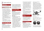
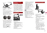
1

Fastening this product to the factory 
radio-mounting bracket.

Position this product so that its screw 
holes are aligned with the screw holes 
of the bracket, and tighten the screws at 
three locations on each side.
Use either the truss head screws (5 mm 
× 8 mm) or flush surface screws (5 mm × 
9 mm), depending on the shape of the 
bracket’s screw holes.

 Factory radio-mounting bracket
 If the pawl interferes with 

installation, you may bend it down 
out of the way.

 Dashboard or console
 Truss head screw or flush surface 

screw
Be sure to use the screws supplied 
with this product.

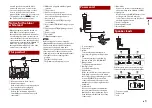
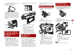
Install the microphone in a place where 
its direction and distance from the driver 
make it easiest to pick up the driver’s 
voice.

Be sure to turn off (ACC OFF) the product 
before connecting the microphone.

Depending on the vehicle model, the 
microphone cable length may be too 
short when you mount the microphone 
on the sun visor. In such cases, install the 
microphone on the steering column.

1

Fit the microphone lead into the 
groove.

Installation using the 

screw holes on the side 

of this product

Leave ample 
space

5 cm

5 cm

Installing the 

microphone

Mounting on the sun 

visor

Summary of Contents for MVH-2300NEX

Page 1: ...English Français Español MVH 2300NEX RDS AV RECEIVER AUTORADIO MULTIMÉDIA RDS AV RECEPTOR RDS Installation Manual Manuel d installation Manual de instalación ...

Page 2: ...iring away in such so that they will not obstruct or hinder driving Connection Precautions Your new product and this manual Important safeguards Precautions before connecting the system Make sure that the cables and wires will not interfere with or become caught in any of the vehicle s moving parts especially the steering wheel shift lever parking brake sliding seat tracks doors or any of the vehi...

Page 3: ...adapter you will need to first flash the Maestro module with the appropriate vehicle and head unit firmware You can find the device number that is required for the activation on the followings refer to the Operation Manual The label on the packaging of this product The label on this product The Firmware Information screen Notice for the blue white lead This product To power supply Power cord Yello...

Page 4: ... output NW Rear speaker STD Middle range speaker NW To Front output STD To high range output NW Front speaker STD High range speaker NW To subwoofer output STD To low range output NW Subwoofer STD Low range speaker NW Power amp sold separately Without internal amp With internal amp NOTE Select the appropriate speaker mode between standard mode STD and network mode NW For details refer to the Opera...

Page 5: ...layed while backing or checking the rear of the vehicle may differ slightly Rear view camera ND BC8 sold separately To video output RCA cable supplied with ND BC8 This product Brown R C IN Power supply Power cord Violet white REVERSE GEAR SIGNAL INPUT Refer to Power cord on page 3 NOTES Connect only the rear view camera to R C IN Do not connect any other equipment Some appropriate settings are req...

Page 6: ...ght such as on top of the dashboard Places that may be exposed to rain such as close to the door or on the vehicle s floor Install this product horizontally on a surface within 0 to 30 degrees tolerance within 5 degrees to the left or right Improper installation of the unit with the surface tilted more than these tolerances increases the potential for errors in the vehicle s location display and m...

Page 7: ...ot recognise the driver s voice if the sun visor is in the down position 1 Detach the microphone base from the microphone clip by sliding the microphone base while pressing the tab Tab Microphone base 2 Mount the microphone on the steering column Double sided tape Clamps Use separately sold clamps to secure the lead where necessary inside the vehicle NOTE Keeping it away from the steering wheel In...

Page 8: ... prendre avant de connecter le système contact des pièces métalliques cela peut causer un court circuit très dangereux Il est extrêmement dangereux de laisser les câbles s enrouler autour de la colonne de direction ou du levier de vitesse Assurez vous d installer ce produit ses câbles et ses fils à l écart de sorte qu ils ne gênent pas la conduite Assurez vous que les câbles et fils ne gêneront pa...

Page 9: ... bleu blanc Ce produit Contactez votre détaillant au sujet des appareils de navigation connectables Prise d antenne Sortie de caisson d extrêmes graves STD Sortie de sons graves NW Sortie arrière STD Sortie de sons moyens NW Sortie avant STD Sortie de sons aigus NW Alimentation Fusible 10 A Entrée d adaptateur iDatalink REMARQUE Avant d utiliser et ou de connecter l adaptateur iDatalink Maestro vo...

Page 10: ...rleur arrière STD ou les signaux de haut parleur de sons moyens et de haut parleur de sons aigus NW sont émis par les fils de haut parleurs lorsque cette connexion est utilisée Commande à distance du système Connectez au câble bleu blanc Amplificateur de puissance vendu séparément Connectez au câble RCA vendu séparément Vers la sortie arrière STD Vers la sortie de sons moyens NW Haut parleur arriè...

Page 11: ...image affichée à l écran soit inversée Avec la caméra de recul vous pouvez garder un œil sur la remorque ou regarder derrière en reculant dans un stationnement étroit Ne l utilisez pas à des fins de divertissement Les objets de l affichage de recul peuvent sembler plus proches ou plus éloignés que la distance réelle La zone d image des images plein écran affichées en reculant ou en vérifiant à iPh...

Page 12: ...ut dispositif de sécurité du véhicule y compris les coussins de sécurité gonflables ou les boutons de feux de détresse ou iii d affecter la capacité du conducteur à utiliser le véhicule de façon sécuritaire N installez pas ce produit devant ou près d un emplacement de déploiement des coussins de sécurité gonflables du véhicule que ce soit le tableau de bord une portière ou un pilier Reportez vous ...

Page 13: ...nnecter le microphone Suivant le modèle de véhicule la longueur du câble de microphone peut être insuffisante lorsque vous montez le microphone sur le pare soleil Le cas échéant installez le microphone sur la colonne de direction Installation à l aide des trous de vis sur le côté de ce produit Laissez un espace suffisant 5 cm 5 cm Installer le microphone 1 Placez le fil de microphone dans la rainu...

Page 14: ...8Fr Régler l angle du microphone ...

Page 15: ...9 Fr Français ...

Page 16: ...or Si se rompe el aislamiento del cable amarillo como consecuencia del contacto con partes metálicas puede producirse un cortocircuito y por ende un peligro considerable Es extremadamente peligroso que los cables se enrollen en la columna de dirección o la palanca de cambios Asegúrese de instalar este producto sus cables y los hilos de tal manera que no obstruyan ni obstaculicen la conducción del ...

Page 17: ...tro dispositivo electrónico en el vehículo Piezas metálicas de la carrocería del vehículo 1 No se suministra para esta unidad Posición ACC Sin posición ACC Aviso para el cable azul blanco Este producto Comuníquese con su distribuidor para hacer consultas sobre la unidad de navegación conectable Clavija de conexión de la antena A la salida del subwoofer STD a la salida de rango bajo NW A la salida ...

Page 18: ...na que no estén conectados a ninguna bocina Cables de bocinas Importante Los cables de bocinas no se utilizan cuando esta conexión está en uso Importante Las señales de bocina Delantera y bocina Trasera STD o las señales de bocina de rango medio y bocina de rango alto NW se emiten desde los cables de bocinas cuando esta conexión está en uso Control remoto del sistema Conéctelo al cable Azul blanco...

Page 19: ...la palanca de cambios a REVERSA R El modo Vista de cámara también le permite observar qué está detrás de usted cuando conduce ADVERTENCIA USE ESTA FUNCIÓN SOLO PARA DAR MARCHA ATRÁS O VER UN REFLEJO DE LA CÁMARA DE VISIÓN TRASERA CUALQUIER OTRO USO PODRÍA PRODUCIR LESIONES O DAÑOS PRECAUCIÓN Es posible que la imagen de la pantalla se vea invertida Con la cámara de visión trasera puede observar los...

Page 20: ... piezas internas de este producto o podrían aflojarse y provocar el desprendimiento del producto No instale este producto donde quizá i obstruya la visión del conductor ii afecte el funcionamiento de cualquiera de los sistemas de operación del vehículo relacionados con la seguridad como las bolsas de aire los botones de luces de advertencia intermitentes o iii afecte la capacidad del conductor de ...

Page 21: ...ecta para facilitar al máximo la detección de la voz del conductor Asegúrese de apagar ACC OFF el producto antes de conectar el micrófono Según el modelo del vehículo el largo del cable del micrófono puede ser muy corto cuando monte el micrófono en la visera Instalación mediante los orificios de tornillo del lateral de este producto Dejar un espacio amplio 5 cm 5 cm Instalación del micrófono En es...

Page 22: ...8Es Ajuste del ángulo del micrófono ...

Page 23: ...9 Es Español ...

Page 24: ... 2017 PIONEER CORPORATION All rights reserved 2017 PIONEER CORPORATION Tous droits de reproduction et de traduction réservés CRD5017 A UC ...

Reviews: