background image

PD-217

15

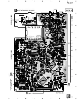
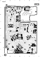
MOTHER BOARD ASSY

PWM2140

PWM2139

PWM2139

NSP

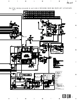
SUB BOARD ASSY

PWX1400

PWX1400

PWX1400

NSP

        DISPLAY BOADR ASSY

PWZ2937

PWZ2937

PWZ2937

NSP

        SW BOARD ASSY

PWZ2942

PWZ2942

PWZ2942

NSP

         HP BOARD ASSY

PWZ2949

PWZ2949

PWZ2949

NSP

SINGLE MECHANISM ASSY

PXA1593

PXA1593

PXA1593

NSP

       SERVO MECHANISM ASSY

PXA1596

PXA1596

PXA1596

NSP

              MECHANISM BOARD ASSY

PWX1192

PWX1192

PWX1192

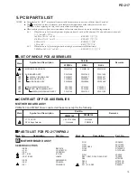
5. PCB PARTS LIST

NOTES :

÷

Parts marked by “ NSP ” are generally unavailable because they are not in our Master Spare Parts List.

÷

The 

 mark found on some component parts indicates the importance of the safety factor of the part.

Therefore, when  replacing, be sure to use parts of identical designation.

÷

When ordering resistors, first convert resistance values into code form as shown in the following examples.
Ex. 1

When there are 2 effective digits (any digit apart from 0), such as 560 ohm and 47k ohm (tolerance is shown by
J = 5%, and K = 10%).
560 


=

 56 

×

 10

 1 

=

 561 ................................................... RD1/4PU 

5


6


1

 J

47k 


=

 47 

×

 10 

3


=

 473 .................................................. RD1/4PU 

4


7


3

 J

0.5 


=

 R50 ...................................................................... RN2H 

Â


5


0

 K


=

 1R0 ......................................................................... RS1P 

1


Â


0

 K

Ex. 2

When there are 3 effective digits (such as in high precision metal film resistors).
5.62k 


=

 562 

×

 10 

1


=

 5621 ........................................... RN1/4PC 

5


6


2


1

 F

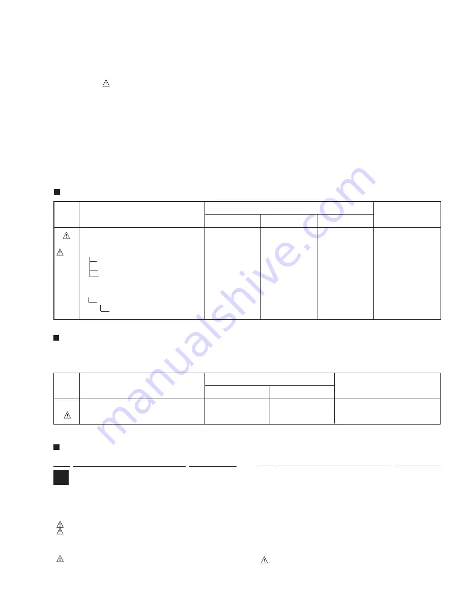
   LIST OF WHOLE PCB ASSEMBLIES

   CONTRAST OF PCB ASSEMBLIES

MOTHER BOARD ASSY

PWM2140 and PWM2139 are constructed the same except for the following:

C173, C5321

CKCYF103Z50

Not used


S5 Voltage Selector

Not used

PSB1006

Mark

Remarks

Symbol and Description

Part No.

PWM2140

PWM2139

Mark

Symbol and Description

Part No.

WPWXJ

RDXJ

RLXJ

Remarks

MOTHER BOARD ASSY

B

Mark No.

Description

Part  No.

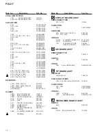
   PARTS LIST FOR PD-217/WPWXJ

Mark No.

Description

Part  No.

SEMICONDUCTORS

IC406

BA15218

IC151

CXA1782CQ

IC301

CXD2519Q

IC31, IC34

ICP-N10

IC201, IC202

LA6520

IC405

NJM4558D-D

IC351

PD4835A

IC21

PQ05RR12

Q151

2SA854S

Q391

2SC1740S

Q403, Q404

2SD2144S

Q152

DTA124ES

Q405

DTC124ES

Q341

2SK246

D341, D351, D352, D395– D397

1SS355

D54

MTZJ18B

D359

MTZJ5.1B

D218

MTZJ6.2B

D11– D14, D52

S5688G

Summary of Contents for PD-217

Page 1: ... VIEWS AND PARTS LIST 3 3 SCHEMATIC DIAGRAM 8 4 PCB CONNECTION DIAGRAM 12 5 PCB PARTS LIST 15 6 ADJUSTMENT 17 7 GENERAL INFORMATION 25 7 1 DISPLAY 25 7 2 BLOCK DIAGRAM 26 8 PANEL FACILITIES AND SPECIFICATIONS 27 THIS MANUAL IS APPLICABLE TO THE FOLLOWING MODEL S AND TYPE S Power Requirement Type Model PD 217 The voltage can be converted by the following method COMPACT DISC P AYER Û S ANDB N TAND Y...

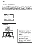
Page 2: ... objective lens with the naked eye will cause exposure to a Class 1 laser beam IMPORTANT THIS PIONEER APPARATUS CONTAINS LASER OF CLASS 1 SERVICING OPERATION OF THE APPARATUS SHOULD BE DONE BY A SPECIALLY INSTRUCTED PERSON LASER DIODE CHARACTERISTICS MAXIMUM OUTPUT POWER 5 mw WAVELENGTH 780 785 nm Refer to page18 LABEL CHECK Additional Laser Caution 1 SAFETY INFORMATION This service manual is inte...

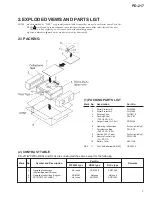
Page 3: ...or L PHA1290 3 Packing Case PHG2370 4 Packing Sheet Z23 007 750 600 0 5 5 Output Cable L 1 0m PDE1248 6 Operating Instructions See Contrast table 2 7 Polyethylene Bag Z21 038 340 230 0 03 8 Caution 220V Label See Contrast table 2 9 Remote Control Unit PWW1158 CU PD112 10 Battery Cover AZA7148 NSP 11 Dry Cell Batteries AA R6P VEM 013 2 CONTRAST TABLE PD 217 WPWXJ RDXJ and RLXJ are constructed the s...

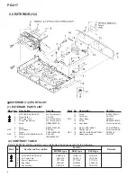
Page 4: ...r Base PNA2177 14 Screw BBZ30P060FMC 15 Rear Base See Contrast table 2 16 Binder SKB 90BK ZCA SKB90BK 17 Caution Label See Contrast table 2 NSP 18 HEADPHONE BOARD ASSY PWZ2949 19 Headphone Knob PAC1707 2 CONTRAST TABLE PD 217 WPWXJ RDXJ and RLXJ are constructed the same except for the following Part No Remarks Mark WPWXJ type RDXJ type RLXJ type 1 MOTHER BOARD ASSY PWM2140 PWM2139 PWM2139 No Symbo...

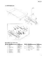
Page 5: ...w BBZ30P080FZK 4 Tray Name Plate PNW2923 5 Screw IBZ30P080FCC 6 Display Window PAM1666 7 Name Plate PAM1776 8 Function Panel PNW2911 9 Mode Button PAC1796 10 Operate Button PAC1798 11 LED Lens PNW2019 12 Power Button PAC1708 NSP 13 SW BOARD ASSY PWZ2942 14 Screw PPZ30P100FMC NSP 15 DISPLAY BOARD ASSY PWZ2937 16 32P F F C 30V PDD1041 17 10 Key PAC1797 ...

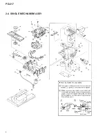
Page 6: ...PD 217 6 2 4 SINGLE MECHANISM ASSY ...

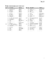
Page 7: ...older PNW1608 22 Screw JFZ20P030FNI 23 Screw JFZ17P025FZK 24 Gear 3 PNW2054 25 Gear 2 PNW2053 26 Washer WT12D032D025 27 PICK UP ASSY S PEA1335 28 Guide Bar PLA1094 29 Gear 1 PNW2052 30 Gear Stopper PNB1303 31 Screw BBZ20P060FMC 32 FFC Holder PNW2734 33 Screw BPZ26P100FMC 34 Earth Lead Unit PDF1104 35 Screw BBZ26P060FMC NSP 36 MECHANISM BOARD ASSY PWX1192 37 Clamp Magnet PMF1014 38 Yoke PNB1216 NSP...

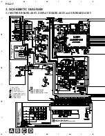
Page 8: ...ES C D B A PICK UP ASSY PEA1335 SERVO MECHANISM ASSY PXA1596 MECHANISM BOARD ASSY PWX1192 SINGLE MECHANISM ASSY PXA1593 PWM2140 WPWXJ TYPE PWM2139 RDXJ and RLXJ TYPES WPWXJ TYPE D801 SIGNAL ROUTE AUDIO SIGNAL AUDIO SIGNAL FOCUS SERVO LOOP TRACKING SERVO LOOP CARRIAGE SERVO LOOP SPINDLE DRIVE LOADING DRIVE SPINDLE MOTOR ASSY PEA1235 CARRIAGE MOTOR ASSY PEA1246 CONNECTOR ASSY RDE1043 3 SCHEMATIC DIA...

Page 9: ...27 28 29 4 9 4 9 25 8 26 2 30 31 32 33 34 4 9 4 8 4 0 2 5 35 36 37 38 39 4 9 4 9 1 3 1 0 40 4 8 4 9 2 9 4 0 2 3 0 1 0 0 0 1 0 0 1 3 1 0 PIN No Volta ge V PLAY STOP 41 42 43 44 45 46 47 48 49 1 0 1 2 50 51 52 53 54 4 9 1 2 4 9 4 9 55 56 57 58 59 4 9 4 9 0 1 0 1 60 4 9 4 9 4 9 2 3 2 3 2 2 2 2 0 1 0 1 4 9 4 9 1 3 1 0 1 3 1 0 5 0 5 0 1 2 1 0 0 9 1 0 1 2 1 0 1 2 5 0 1 0 4 9 6 8 4 9 61 62 63 64 0 1 0 1 ...

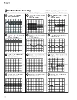
Page 10: ... MODE FODR 1V div 200msec div IC202 Pin 4 PLAY MODE FODR 1V div 1msec div IC202 Pin 3 PLAY MODE TRDR 500mV div 1msec div IC202 Pin 3 50T JUMP 1 MODE TRDR 500mV div 1msec div IC201 Pin 9 PLAY MODE SPDR 1V div 50msec div IC201 Pin 9 TRACK SEARCH MODE SPDR 2V div 50msec div VC VC VC VC VC GND GND GND GND GND GND GND B Waveforms Mother Board Assy Note The encircled numbers denote measuring point in th...

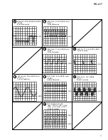
Page 11: ...E 1kHz LOUT 1 1V div 200msec div IC301 Pin 54 PLAY MODE 1kHz BCK 2V div 500nsec div IC301 Pin 50 PLAY MODE 1kHz LRCK 2V div 10 µsec div IC301 Pin 52 PLAY MODE 1kHz PCMD 2V div 500nsec div TRACK SEARCH MODE Upper TP1 Pin 1 RF 1V div Lower IC151 Pin 23 C OUT 2V div 50 µsec div IC301 Pin 27 PLAY MODE MDP 2V div 2 µsec div GND GND GND GND GND GND GND GND GND ...

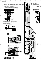
Page 12: ...respective destinations be sure to check with the schematic diagram 4 View point of PCB diagrams Symbol In PCB Diagrams Symbol In Schematic Diagrams Part Name B C E D D G G S S B C E B C E D G S B C E B C E B C E Transistor Transistor with resistor Field effect transistor Resistor array 3 terminal regulator Capacitor Connector P C Board Chip Part SIDE A SIDE B C D A E CARRIAGE MOTOR M SPINDLE MOTO...

Page 13: ... BOARD ASSY PNP1424 B A CN610 AC POWER CORD To PICKUP ASSY E J501 To LOADING MOTOR and CLAMP SW C CN701 VR151 VR152 Q391 Q452 Q454 Q404 Q403 Q453 Q451 Q405 IC406 IC405 IC31 IC401 IC34 Q341 Q151 Q152 IC202 IC21 Q321 VR153 VR154 VR155 VR156 SIDE A ...

Page 14: ...PD 217 14 A B C D 1 2 3 4 1 2 3 4 B MOTHER BOARD ASSY PNP1424 B IC301 IC151 IC351 SIDE B B ...

Page 15: ... ohm and 47k ohm tolerance is shown by J 5 and K 10 560 Ω 56 101 561 RD1 4PU 5 6 1 J 47k Ω 47 10 3 473 RD1 4PU 4 7 3 J 0 5 Ω R50 RN2H Â 5 0 K 1 Ω 1R0 RS1P 1 Â 0 K Ex 2 When there are 3 effective digits such as in high precision metal film resistors 5 62k Ω 562 10 1 5621 RN1 4PC 5 6 2 1 F LIST OF WHOLE PCB ASSEMBLIES CONTRAST OF PCB ASSEMBLIES MOTHER BOARD ASSY PWM2140 and PWM2139 are constructed t...

Page 16: ...RCP1049 Other Resistors RD1 4PU J OTHERS CN202 MT 4P CONNECTOR 173981 4 CN205 MT 5P CONNECTOR 173981 5 CN351 32P FFC CONNECTOR HLEM32S 1 JA401 2P JACK PKB1023 JA393 JACK PKN1005 X341 XTAL RES 16 9344 MHz PSS1008 CN201 CONNECTOR 6P RKP 533 CN131 CONNECTOR SLW16S 1C7 X351 CERAMIC RESONATOR VSS1014 4 19MHz CN401 3P JUMPER CONNECTOR 52147 0310 TERMINAL RKC 061 DISPLAY BOARD ASSY SEMICONDUCTORS D701 D7...

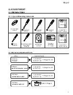
Page 17: ... MOTOR 1 2 3 4 5 6 7 8 9 10 11 12 ADJ Page 6 CD TEST DISC YEDS 7 screwdriver small Precise screwdriver screwdriver medium screwdriver large 39 kΩ 0 001µF Low frequency oscillator Dual trace oscilloscope 10 1 probe Low pass filter 1 39 kΩ 0 001µF 56 kΩ 0 001µF Low pass filter 2 56 kΩ 0 001µF Ball point hexagon wrench size 1 5mm GGK1002 Page 19 24 1 3 5 6 7 8 9 10 11 12 1 2 3 4 5 6 7 8 9 10 11 12 Pa...

Page 18: ...T SCREW Tangential tilt direction Stop all operation 6 2 1 How to Start Cancel Test Mode 6 2 2 Adjustment Location 6 2 ADJUSTMENT TEST MODE W107 W108 Short point MOTHER BOARD ASSY Laser diode LIGHTS UP Focus servo CLOSE TEST CN201 TP1 1 RF 2 TR ER 3 TR IN 4 VC 5 FO IN 6 FO ER VR151 TR GAIN VR152 FO GAIN VR153 RF LEVEL VR154 FO OFFSET VR155 TR BAL VR156 FO BEST PROGRAM inwards outwards Pickup Move ...

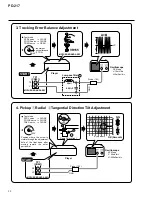
Page 19: ... div H 5mSec div Player FE VC START TP1 CN201 TE VC Locate null Counterclockwise Maximum amplitude 39kΩ 0 001µF Prove 10 1 GND Low pass filter 1 MOTHER BOARD ASSY MOTHER BOARD ASSY 6 2 3 Check and Adjustment 4 Grating Turn counterclockwise from null 8 cm DISC PLAY Test mode FOCUS servo SPDL servo TRKG servo CLOSE CLOSE OPEN Position at whitch the adjust ment hole is visible outside the disc when m...

Page 20: ...1 TRK VC A B GND GND Player TP1 CN201 RF VC START Probe 10 1 Oscilloscope AC Mode V 20mV div H 200nSec div NG OK Smooth Eye pattern 4 Pickup 1Radial 2Tangential Direction Tilt Adjustment MOTHER BOARD ASSY MOTHER BOARD ASSY MOTHER BOARD ASSY TEST DISC PLAY Test mode SPDL servo FOCUS servo TRKG servo CLOSE CLOSE CLOSE Position where the screw is visible through the adjustment hole of the float base ...

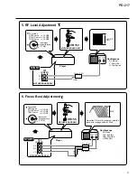
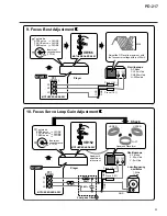
Page 21: ...e 10 1 Player START TP1 CN201 RF VC MAX GND Prove 10 1 FE 6 1 4 GND Adjust the RF level to maximum with the focus error voltage within 150mV MOTHER BOARD ASSY MOTHER BOARD ASSY MOTHER BOARD ASSY Test mode SPDL servo FOCUS servo TRKG servo CLOSE CLOSE CLOSE TEST DISC PLAY Innermost circumference 1 TRK VR156 MOTHER BOARD ASSY Test mode SPDL servo FOCUS servo TRKG servo CLOSE CLOSE CLOSE TEST DISC PL...

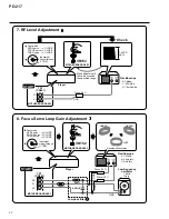
Page 22: ...w frequency oscillator 1 2kHz 1Vp p GND GND Prove 10 1 56kΩ 0 001µF Low pass filter 2 100kΩ FE Make adjustment if the value exceeds the specified range Check 6 5 4 Lissajous Waveform MOTHER BOARD ASSY MOTHER BOARD ASSY VR153 MOTHER BOARD ASSY Test mode SPDL servo FOCUS servo TRKG servo CLOSE CLOSE CLOSE TEST DISC PLAY Innermost circumference 1 TRK Test mode SPDL servo FOCUS servo TRKG servo CLOSE ...

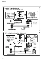
Page 23: ...ARD ASSY VR156 MOTHER BOARD ASSY Test mode SPDL servo FOCUS servo TRKG servo CLOSE CLOSE CLOSE TEST DISC PLAY Innermost circumference 1 TRK UNDER Oscilloscope X Y Mode X 20mV div Y 5mV div GND Prove 10 1 Player START TP1 CN201 FI VC UPPER JUST Low frequency oscillator 1 2kHz 1Vp p GND GND Prove 10 1 56kΩ 0 001µF Low pass filter 2 100kΩ FE 6 5 4 Lissajous Waveform MOTHER BOARD ASSY Test mode SPDL s...

Page 24: ...VR156 MOTHER BOARD ASSY Test mode SPDL servo FOCUS servo TRKG servo CLOSE CLOSE CLOSE TEST DISC PLAY Innermost circumference 1 TRK 12 Tracking Servo Loop Gain Adjustment UNDER Oscilloscope X Y Mode X 20mV div Y 10mV div GND Prove 10 1 Player START TP1 CN201 TI VC UPPER JUST Low frequency oscillator 1 2kHz 1Vp p GND GND Prove 10 1 100kΩ TE 2 3 4 Lissajous Waveform MOTHER BOARD ASSY Test mode SPDL s...

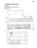
Page 25: ...PD 217 25 7 GENERAL INFORMATION 7 1 DISPLAY 7 PEL1085 V701 DISPLAY BOARD ASSY 7 FL INDICATOR TUBE Pin Assignment Pin Connection Grid Assignment Anode Connection ...

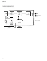
Page 26: ...y SERVO CONTROLLER IC151 CXA1782CQ DECODER DAC IC301 CXD2519Q LPF IC405 NJM4558D D AUDIO SIGNAL CPU IC351 PD4835A AMP IC201 IC202 LA6520 Spindle Carriage Loading etc Focus Tracking M DISPLAY FUNCTION KEY POWER SUPPLY DECK SYNCHRO HEADPHONE JACK ...

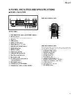
Page 27: ...TE scan button OPEN CLOSE button 0 Play Pause button 6 Stop button 7 Track Manual search buttons 4 1 PROGRAM button Headphones jack PHONES Headphones volume control LEVEL 1 2 3 4 5 6 7 8 9 0 OUTPUT LEVEL RANDOM HI LITE 1 4 7 8 3 1 2 3 4 5 6 7 8 9 10 10 PROGRAM Î COMPACT DISC PLAYER REMOTE CONTROL UNIT REMOTE CONTROL UNIT Remote control buttons with the same names or marks as buttons on the front p...

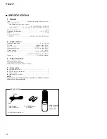
Page 28: ...re EIAJ Dynamic range 96 dB or more EIAJ Harmonic distortion 0 003 or less EIAJ Output voltage 2 0 V EIAJ Wow and flutter Limit of measurement 0 001 W PEAK or less EIAJ Channels 2 channel stereo 3 Output terminal Audio line output jacks CD DECK SYNCHRO jack Headphones jack with volume control 4 Accessories Remote control unit 1 AA R6P dry cell batteries 2 Output cable 1 Operating instructions 1 NO...

Reviews: