138
PDP-503CMX, PDP-503MXE, PDA-5002
7.1.4 DISASSEMBLY
1
1
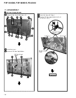
Remove the Rear Case (50M).(Screws
×
20)
2
Remove four screws.
3
Remove the SW Power Supply Module.
SW Power Supply Module
Diagnosis
4
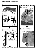
Insert it and reduce the Clamper.
Clamper
Sub Frame L
Slit
SW Power Supply
Module
SW Power Supply
Module
Sub Frame R
5
Insert the SW Power Supply Module into the slit
of Sub Frame L and R.
4
3
1
1
1
1
1
1
1
1
1
2
2
2
2
1
×
2
1
×
2
1
×
2
×
2
×
2
5
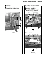
SW Power Supply
Module
1
1
Summary of Contents for PDA-5002
Page 5: ...5 PDP 503CMX PDP 503MXE PDA 5002 ...
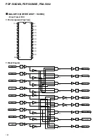
Page 143: ...PDP 503CMX PDP 503MXE PDA 5002 143 Block Diagram Pin Function ...
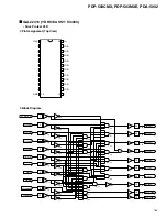
Page 166: ...PDP 503CMX PDP 503MXE PDA 5002 166 Pin Assignment Top View CXA3516R RGB ASSY IC4603 AD PLL IC ...
Page 167: ...PDP 503CMX PDP 503MXE PDA 5002 167 Block Diagram ...
Page 168: ...PDP 503CMX PDP 503MXE PDA 5002 168 Pin Function ...
Page 169: ...PDP 503CMX PDP 503MXE PDA 5002 169 ...

