36
610
D
D
A
93.4
52.5
52.5
C
10
1022
21.6
25
B
10
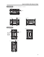
Avoid blocking or
covering this area
on the upper and
lower sides.
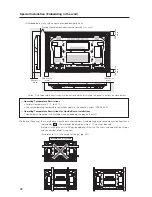
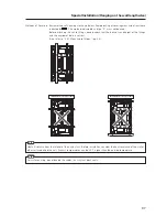
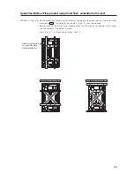
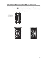
Attach so that the fan is on the left
side when viewed from the rear.
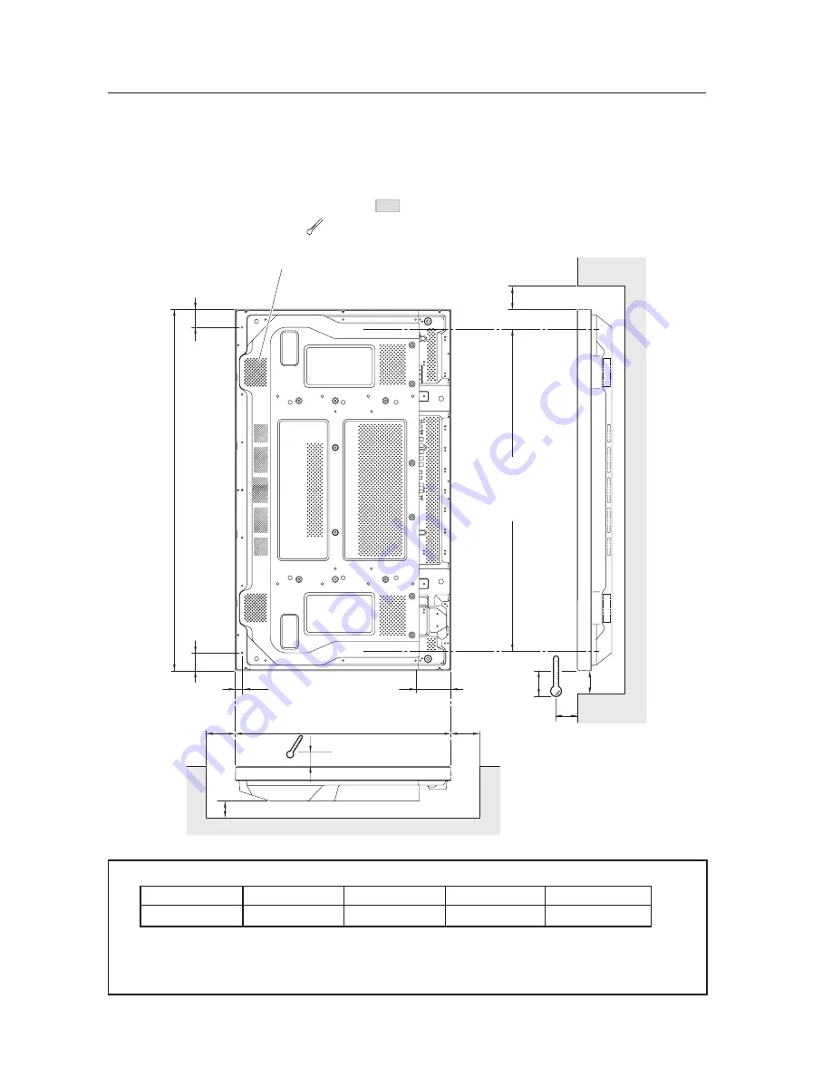
Special Installation (Hanging on the wall lengthwise)
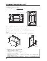
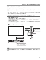
3.4.6 Hanging on the wall lengthwise
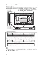
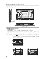
Carefully read the following imformation before attempting to mount the unit on the wall. Observe the various limitations
specified below.
Be sure to mount the unit so that twisting, bending, or any other deformation does not exceed 4 mm.
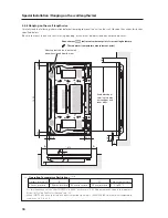
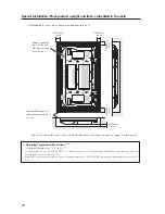
Shaded areas
indicate attachment points for mounting hardware.
✩
Operating Temperature Restrictions
(*1, *2)
Distance from wall (A)
B
C
D
Ambient temperature
50 mm or more
100 mm or more
50 mm or more
50 mm or more
0 °C to 35 °C
: Thermometer (temperature measurement point)
*1
For this installation, set the ‘FAN CONTROL’ to ‘MAX’ as shown in “5.4.3 Adjustment and Setting in the Integrator
Mode 14) Cooling Fan Control Setting” (pg. 172).
*2
When INPUT2 has been selected, use input compatible signal up to 1280x1024 (60 Hz) at ambient temperature
condition of 0 °C to 35 °C.


