20
Installation procedure
3.3.3 Wiring
1) Power source connection
• Refer to
Power cord connection
on page 27, 65 of the instruction manual (PDP-V402EA).
• For power source capacity, see the description given in “3.1 Installation environment, 11) Power requirements”
in this manual.
2) Signal cable connection
(1) Connecting to a PC
• See the description given in
Connecting to a PC
, on pp. 21 to 26, 59 to 64 of the instruction manual
(PDP-V402EA).
(2) Connecting to a video cassette recorder
• See the description given in
Connection to a video cassette recorder
, on pp. 28 to 33 , 66 to 71 of the
instruction manual (PDA-4004).
(3) Precautions
• Use coaxial cables. For video signals, use the 3C-2V for lengths of 15 m or less, and the 5C-2V for lengths of
30 m or less. Since data signals are more easily degraded than video signals, use a thick cable (e.g. a 5C-2V
cable) for data communications, even for lengths of 15 m or less. Try to minimize the distance between the
signal transmission device and the plasma display unit.
• If a video cable is wired close to a dimmer, neon tube, air conditioner, or other device, or if it is wired in
parallel to a cable television cable, display performance may be affected.
3) Treatment of wires
• For long-term or permanent installations, rather than short-term installations for specific events, use wires of
the proper length, carefully considering the placement of all other wires.
• Place wires so that no load or force is applied to the connecting terminals. For short-term use, wires may be
bundled with string. For long-term installations, form wire bunches using cable clamps.
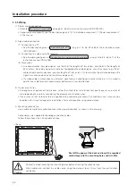
4) Mounting cable clamp
Use a cable clamp to form cable bunches in the upward direction, as shown in the drawing.
Cable clamps are supplied for bundling connection cables.
Follow these steps when using cable clamps:
Caution
Peel off the label covering the mounting holes before attaching the cable clamps.
When cables are inserted in a cable clamp, keep the clamp at least 10 cm from the wall to allow
ventilation.
<Back>
Peel off the paper at the back and insert the supplied
cable clamp into the mounting holes until it clicks.
Summary of Contents for PDK-5008
Page 5: ...5 Features ...
Page 11: ...11 Remote control ...
Page 21: ...21 Installation procedure ...
Page 57: ...57 Special installation Installation under the floor ...
Page 85: ...85 How to mount standard optional items PDK 4001 ...
Page 91: ...91 How to mount standard optional items PDK 4002 ...
Page 97: ...97 How to mount standard optional items PDK 4004 ...
Page 115: ...115 How to mount standard optional items PDK 5008 PDK 5008FT ...
Page 153: ...153 How to mount standard optional items Precautions for installing the optional speaker ...
Page 161: ...161 Before making adjustments ...

